A milling machine sliding platform for placing workpieces

A technology for sliding platforms and workpieces, applied in metal processing machinery parts, metal processing equipment, manufacturing tools, etc., can solve problems such as affecting processing quality, poor coordination between worktable and guide rail, etc., to improve product processing quality and facilitate Flexible installation and disassembly to ensure the effect of accuracy

Active Publication Date: 2020-04-24
安徽鹏睿智能科技有限公司
View PDF1 Cites 1 Cited by
  • Summary
  • Abstract
  • Description
  • Claims
  • Application Information

AI Technical Summary

Problems solved by technology

[0006] The purpose of the present invention is to overcome the disadvantages in the prior art that the poor cooperation between the workbench and the guide rail easily affects the processing quality, and provides a milling machine sliding platform for placing workpieces. Through the optimized design of the workbench and guide rail structure, It helps to realize the accurate cooperation between the workbench and the guide rail, ensures the stable and accurate sliding of the workbench, helps to improve the performance of the milling machine, and guarantees its processing effect on the product

Method used


Image

  • A milling machine sliding platform for placing workpieces
  • A milling machine sliding platform for placing workpieces
  • A milling machine sliding platform for placing workpieces

Examples


Embodiment 1

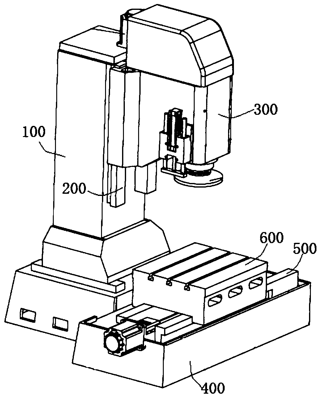
[0036] Such as Figure 1-Figure 4 As shown, the overall structure of the milling machine in this embodiment includes a horizontally arranged bed unit 400, a side of the bed unit 400 is longitudinally provided with a column unit 100, and the column unit 100 is provided with a vertical slide rail unit 200 along the height direction. The slide rail unit 200 is equipped with a head unit 300, which is driven by a power mechanism and can move vertically along the vertical slide rail unit 200, wherein the lower end of the head unit 300 is provided with a milling cutter unit, and the bed unit 400 There are slide rail units 500 in parallel on both sides of the slide rail unit 500, and a workbench unit 600 is slidably fitted on the slide rail unit 500; a horizontal drive unit is also provided on the bed unit 400, and the horizontal drive unit is connected with the workbench unit 600 and used for The workbench unit 600 is driven to move horizontally along the extension direction of the s...

Embodiment 2

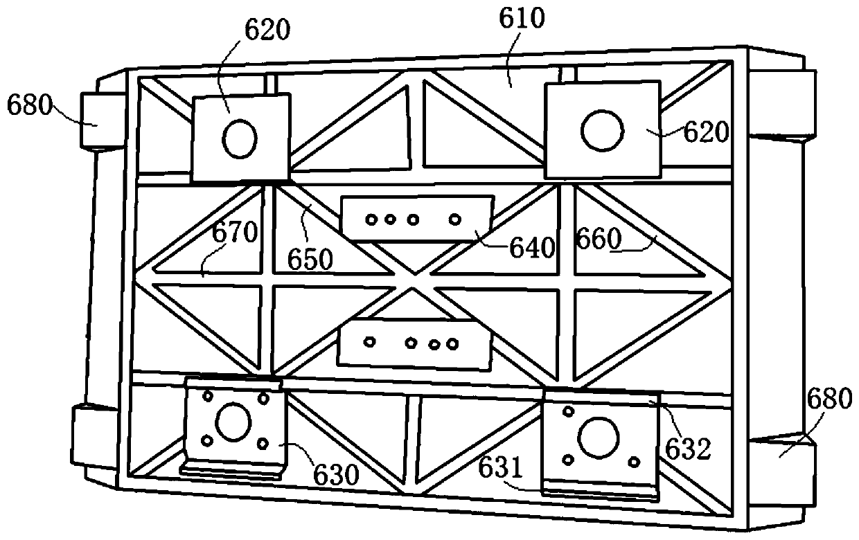
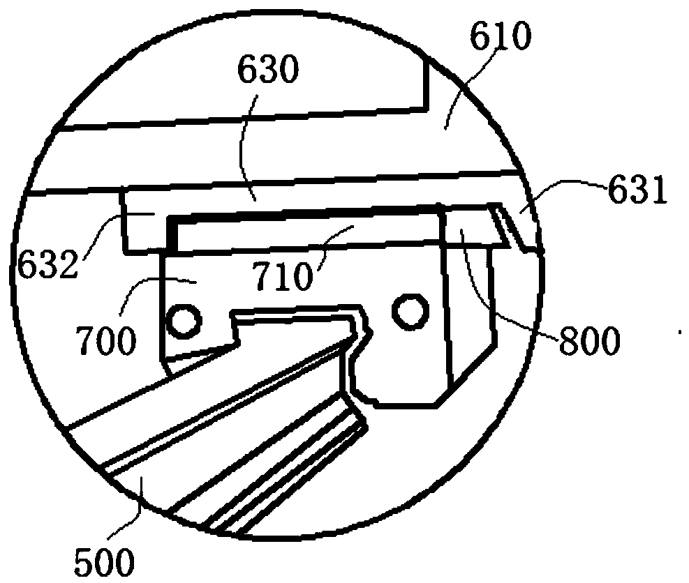
[0042] A milling machine sliding platform for placing workpieces in this embodiment has the same basic structure as in Embodiment 1. Further, in this embodiment, the workbench unit 600 includes a workbench body 610, and the bottom of the workbench unit 600 (i.e., the workbench The bottom of the body 610) is provided with a driven slider 620 and an active slider 630 in parallel on both sides, a sliding seat 700 is provided on the slide rail unit 500, and a protruding mating block 710 is provided on the top of the sliding seat 700. The block 620 and the driving slider 630 are respectively matched with the mating blocks 710 on both sides. Specifically, the driven slider 620 and the driving slider 630 both include a panel attached to the mating block 710, and the driving slider 630 There are also outer clamping plates 631 and inner clamping plates 632 for side clamping and matching the clamping block 710 on both sides of the two sides, the outer clamping plate 631 is an inclined pl...

Embodiment 3

[0046] A milling machine sliding platform for placing workpieces in this embodiment has the same basic structure as in Embodiment 2. Furthermore, in this embodiment, a plurality of reinforcing ribs are provided at the bottom of the workbench body 610, such as figure 2 As shown, there are ribs 650 distributed in an X shape along the diagonal direction. Specifically, two ribs 650 are connected to the four corners of the workbench body 610 and intersect in the middle to form an X shape. Between the bottom sides of the workbench body 610 There are diamond-shaped ribs 660 distributed in a diamond shape, and the four diamond-shaped ribs 660 are connected successively from the middle of the bottom side of the workbench body 610 to form a diamond-shaped structure; the bottom side of the workbench body 610 is also provided with criss-crossing square ribs 670 , a plurality of square ribs 670 are criss-crossed and covered the bottom of the entire workbench body 610. In this embodiment, v...


PUM


Abstract

The invention discloses a milling machine sliding platform for storing workpieces, and belongs to the field of milling machines. The milling machine sliding platform comprises a sliding rail unit anda worktable unit. A sliding seat is arranged on the sliding rail unit in a sliding-fit mode, and the worktable unit is arranged on the sliding seat in a matched mode. The two side walls of the slidingrail unit are each of a side rail structure with the concave middle and two convex sides. The two side walls comprise middle straight sections in the middles correspondingly, the upper portions of the middle straight sections are sequentially provided with first upper arc sections, upper straight sections, second upper arc sections and third upper arc sections from top to bottom, and the lower portions of the middle straight sections are sequentially provided with first lower arc sections, second lower arc sections, third lower arc sections and lower straight sections from top to bottom. Sliding cavities matched with side rails are formed in the bottom of the sliding seat. According to the milling machine sliding platform, the defect that in the prior art, a worktable and guide rails arematched poorly, and consequently, the machining quality is prone to being influenced is overcome, through structural optimal design for the worktable and the guide rails, stable and accurate sliding of the worktable is guaranteed, and the machining effect of the milling machine sliding platform on the workpieces is guaranteed.

Description

technical field [0001] The invention relates to the technical field of milling machines, in particular to a milling machine sliding platform for placing workpieces. Background technique [0002] A milling machine is a machine tool that mainly uses a milling cutter to process various surfaces on a workpiece. Usually, the rotational movement of the milling cutter is the main movement. It can process planes, grooves, and various curved surfaces, gears, etc. In addition to milling planes and grooves In addition to grooves, gear teeth, threads and spline shafts, it can also process more complex profiles, with higher efficiency than planers, and is widely used in machinery manufacturing and repair departments. [0003] The workbench is the workbench used to install the workpiece on the gantry milling machine. There are a number of chutes on the upper end surface of the workbench to facilitate fixing the workpiece. The lower end surface of the workbench is provided with a connectin...

Claims


Application Information

Patent Timeline
Patent Type & Authority Patents(China)
IPC IPC(8): B23Q1/26
CPCB23Q1/26
Inventor 李冬
Owner 安徽鹏睿智能科技有限公司
Why Eureka
Try Eureka