

Clamp for ring part machining and ring part machining method
A technology of ring parts and fixtures, which is applied in the direction of metal processing machinery parts, manufacturing tools, metal processing equipment, etc., can solve the problems affecting the positioning accuracy of ring parts, shorten processing time, improve product quality and precision, and reduce labor intensity. Effect
Pending Publication Date: 2018-12-28
AVIC POWER ZHUZHOU AVIATION PARTS MFG
View PDF0 Cites 5 Cited by
- Summary
- Abstract
- Description
- Claims
- Application Information
AI Technical Summary
Problems solved by technology
The invention provides a fixture and a ring processing method for ring processing to solve the problem that the positioning accuracy of the ring is affected by the reference conversion caused by two clampings during the processing of the ring
Method used
View moreImage
Smart ImageViewing Examples

Examples
Embodiment Construction
Login to View More PUM
 Abstract
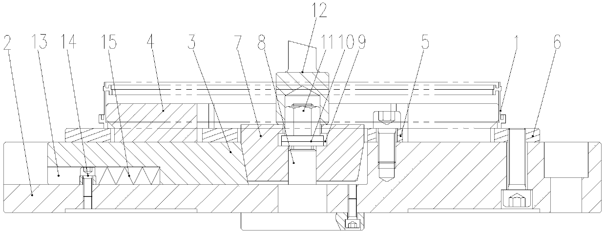
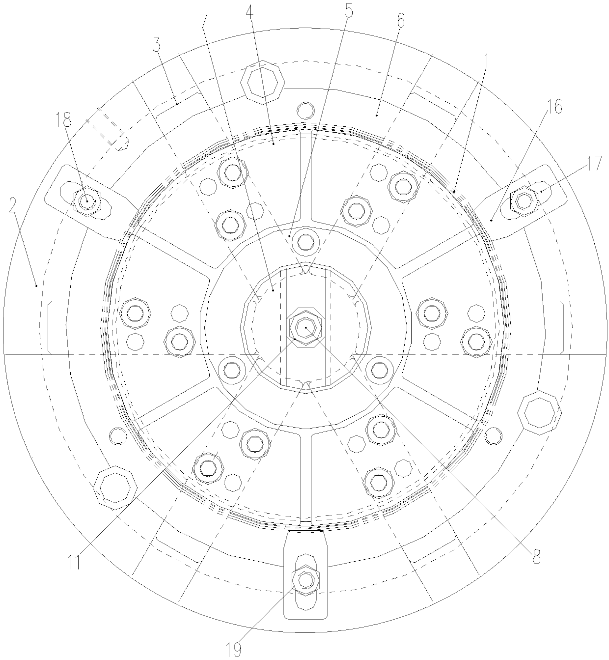
The invention provides a clamp for ring part machining and a ring part machining method. The clamp for ring part machining comprises a base for supporting the bottom surface of the ring part and driving the ring part to rotate, multiple resisting mechanisms arranged at the middle part of the base and respectively moving along the radial direction of the base to resist the inner molded surface of the ring part to enable the ring part to be coaxial with the base, so as to machine the top surface and the outer molded surface of the ring part, and a pressing mechanism arranged at the periphery ofthe base and used for pressing the top surface of the ring part to machine the inner molded surface of the ring part. Before the resisting action of the resisting mechanisms to the inner molded surface of the ring part is withdrawn, the pressing mechanism is used to press the top surface of the ring part, so as to ensure that the locating reference for machining the inner molded surface of the ring part is consistent with the locating reference for machining the top surface and the locating reference for machining the outer molded surface. The pressing mechanism seamlessly replaces the resisting mechanism to limit the ring part to ensure that the position of the ring part cannot be changed, so the ring part is still coaxial with a main shaft during machining of the inner molded surface ofthe ring part.
Description
technical field The invention relates to the technical field of ring piece processing, in particular, to a fixture for ring piece processing and a ring piece processing method. Background technique Ring parts are widely used in metallurgy, petrochemical, aviation, aerospace and other industrial fields. At present, the surface processing of ring parts is divided into two processes. First, the outer surface is clamped with a fixture to process the inner surface, and then the inner surface is clamped with a fixture. The inner surface is used as a reference to process the outer surface. The datum transformation caused by the secondary clamping affects the positioning accuracy of the ring. Since the inner surface and the outer surface are clamped and processed separately, in order to ensure the shape and position tolerance requirements of the ring, the machining accuracy of the two processes needs to be improved, which invisibly greatly increases the processing difficulty of the...
Claims
Login to View More Application Information
Patent Timeline
 Patent Type & AuthorityApplications(China)
IPC IPC(8): B23Q3/06
CPCB23Q3/062
Inventor王熔卜星慧
OwnerAVIC POWER ZHUZHOU AVIATION PARTS MFG