Workpiece carrying device

A technology for handling devices and workpieces, applied in the field of automatic processing devices, can solve the problems of high labor intensity of workers, high production costs, disrupted production order, etc., and achieve the effects of reducing labor intensity, high production efficiency, and ensuring high efficiency and stability.

Inactive Publication Date: 2018-12-28
泸州市龙马潭区鑫泉泡沫塑料有限责任公司
View PDF0 Cites 3 Cited by
  • Summary
  • Abstract
  • Description
  • Claims
  • Application Information

AI Technical Summary

Problems solved by technology

[0002] At present, most enterprises use highly automated production equipment in the production process. A large number of conveyor belts are used in the production process. Corresponding production personnel must be equipped at the joints of each conveyor belt to transport the products conveyed by the previous conveyor belt to the next. The switching of the transmission li

Method used


Image

  • Workpiece carrying device

Examples


Embodiment 1

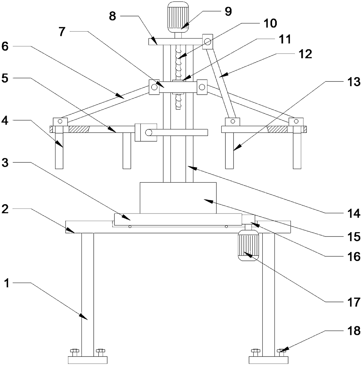
[0024] see figure 1 , a workpiece handling device, comprising a fixed plate 13, including a workbench 2, a rotating seat 15 is installed on the workbench 2, at least two vertical sliding bars 14 are installed on the rotating seat 15, and a positioning platform is installed on the sliding bar 14 8 and the sliding seat 7, the sliding seat 7 is provided with a slide hole through which the slide bar 14 passes, and is sleeved on the slide bar 14 through the slide hole. A connecting rod 6 is provided, and the end of the positioning plate 5 away from the slide bar 14 is provided with a chute. One end of the connecting rod 6 is hinged with the sliding seat 7, and the other end extends into the chute and is hinged with the slide plate 4. The fixed plate 13 is installed in the positioning The plate 5 is close to one end of the slide bar 14 .

[0025] In this example, the sliding seat 7 slides upwards through the cooperation of the slide hole and the slide bar 14, and the pull bar 12 is...

Embodiment 2

[0027] see figure 1 , a workpiece handling device, comprising a fixed plate 13, including a workbench 2, a rotating seat 15 is installed on the workbench 2, at least two vertical sliding bars 14 are installed on the rotating seat 15, and a positioning platform is installed on the sliding bar 14 8 and the sliding seat 7, the sliding seat 7 is provided with a slide hole through which the slide bar 14 passes, and is sleeved on the slide bar 14 through the slide hole. A connecting rod 6 is provided, and the end of the positioning plate 5 away from the slide bar 14 is provided with a chute. One end of the connecting rod 6 is hinged with the sliding seat 7, and the other end extends into the chute and is hinged with the slide plate 4. The fixed plate 13 is installed in the positioning The plate 5 is close to one end of the slide bar 14 .

[0028] There are two positioning platforms 8, and the sliding seat 7 is socketed on the slide bar 14 between the two positioning platforms 8. Th...

Embodiment 3

[0031] see figure 1 , a workpiece handling device, comprising a fixed plate 13, including a workbench 2, a rotating seat 15 is installed on the workbench 2, at least two vertical sliding bars 14 are installed on the rotating seat 15, and a positioning platform is installed on the sliding bar 14 8 and the sliding seat 7, the sliding seat 7 is provided with a slide hole through which the slide bar 14 passes, and is sleeved on the slide bar 14 through the slide hole. A connecting rod 6 is provided, and the end of the positioning plate 5 away from the slide bar 14 is provided with a chute. One end of the connecting rod 6 is hinged with the sliding seat 7, and the other end extends into the chute and is hinged with the slide plate 4. The fixed plate 13 is installed in the positioning The plate 5 is close to one end of the slide bar 14 .

[0032] The workbench 2 is provided with a groove embedded in the ring gear 3, the rotating seat 15 is installed on the ring gear 3, the ring gea...


PUM


Abstract

The invention relates to the field of automatic machining devices, in particular to a workpiece carrying device. The workpiece carrying device comprises a fixing plate and is characterized in that theworkpiece carrying device comprises a worktable, a rotating seat is mounted on the worktable, two or more perpendicular sliding rods are mounted on the rotating seat, and a positioning table and a sliding seat are mounted on the sliding rods; the sliding seat is provided with sliding holes for allowing the sliding rods to penetrate, and the sliding seat is connected to the sliding rods through the sliding holes in a sleeving mode; positioning plates are arrange on the two sides of the sliding rods correspondingly, connecting rods are arranged on the two sides of the sliding seat, and slidinggrooves are formed in the ends, deviating from the sliding rods, of the positioning plates; one ends of the connecting rods are hinged to the sliding seat, and the other ends of the connecting rods extend into the sliding grooves to be hinged to sliding plates; and fixing plates are mounted at the ends, close to the sliding rods, of the positioning plates. The workpiece carrying device can carry and feed workpieces automatically at adjacent conveying belts, the production efficiency is high, the high efficiency and stability of production can be ensured for a long time, and the labor intensityof staff and the production cost of enterprises are lowered.

Description

technical field [0001] The invention relates to the field of automatic processing devices, in particular to a workpiece handling device. Background technique [0002] At present, most enterprises use highly automated production equipment in the production process. A large number of conveyor belts are used in the production process. Corresponding production personnel must be equipped at the joints of each conveyor belt to transport the products conveyed by the previous conveyor belt to the next. The switching of the transmission line of the product between a conveyor belt or adjacent conveyor belts requires manual connection during the transition of the production process. Not only is the labor intensity of the staff high, the production cost is high, and at the same time, it may not be possible to maintain efficient and stable connection for a long time due to human factors. disrupt the production order. Therefore, it is very meaningful for those skilled in the art to desig...

Claims


Application Information

Patent Timeline
IPC IPC(8): B65G47/90
CPCB65G47/902
Inventor 肖启
Owner 泸州市龙马潭区鑫泉泡沫塑料有限责任公司
Why Eureka
Try Eureka