

A swing type pre-limit rod and a vehicle super-height detection method
A detection method and swing-type technology, applied in the field of channel traffic, can solve the problems of damaged vehicles, missed detection and false alarms, high cost, etc., and achieve the effects of reducing vehicle damage, stable and reliable operation, and low maintenance costs
- Summary
- Abstract
- Description
- Claims
- Application Information
AI Technical Summary
Problems solved by technology
Method used
Image

Examples
Embodiment example 1
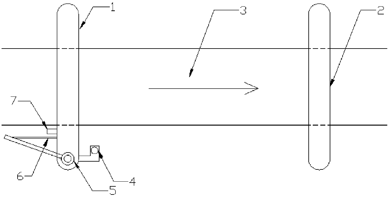
[0049] figure 1 It is a structural schematic diagram of a swing type pre-limit rod according to an implementation example of the present application.
[0050] Such as figure 1 As shown, a swing type pre-limit rod includes a column 5, a swing component 1, and a swing sensor 4; the column 5 is fixedly arranged on the outside of the channel 3; The top of the column 5 and the lower edge are arranged horizontally, extending above the channel 3 and capable of rotating in the horizontal plane; the swing sensor 4 is used to detect the position change of the swing component 1 .
[0051] The rotating shaft of the swinging part 1 is arranged vertically to the ground.
[0052] Both the swinging part 1 and the fixed height-limiting rod 2 are located on the channel 3; The direction indicated by the arrow in channel 3 is the driving direction of the vehicle.
[0053] The distance between the lower edge of the swinging part 1 and the channel 3 is equal to the height limit of the channel 3...
Embodiment example 2
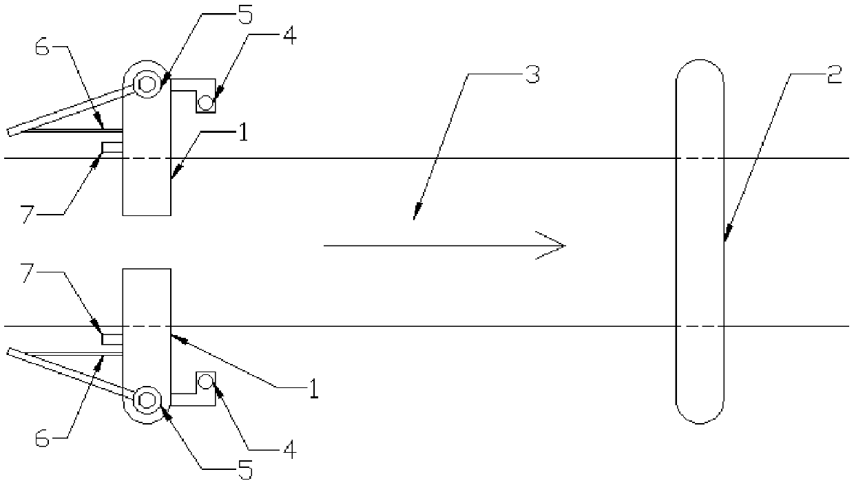
[0067] figure 2 It is a structural schematic diagram of a swing type pre-limit rod according to another implementation example of the present application.
[0068] The difference between the second implementation example and the first implementation example is that in the second implementation example, a pre-limit rod is arranged on both sides of the channel 3, two swing parts 1 are arranged opposite to each other, and a gap is reserved between the two swing parts 1, so that When it swings, it does not collide with each other.
[0069] In the second implementation example, the blocking force of the swinging part 1 to the vehicle is reduced, and the collision force of the swinging part 1 is reduced, making it more durable; double pre-limit levers are set to improve the reliability of the system.
Embodiment example 3
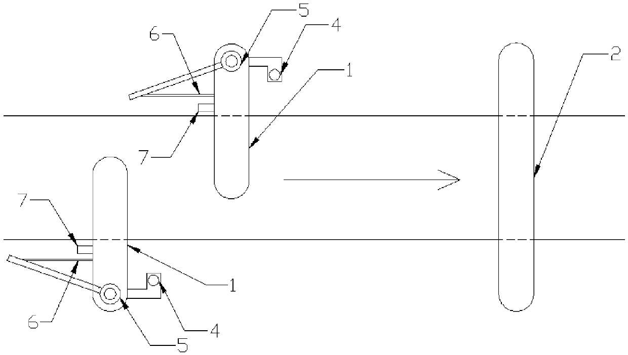
[0071] image 3 It is a structural schematic diagram of a swing type pre-limit rod according to another implementation example of the present application.
[0072] The difference between the third implementation example and the second implementation example is that in the third implementation example, the two pre-limit rods are arranged staggered along the direction of the channel 3, and the length of the two swinging parts 1 extending to the inside of the channel 3 is lengthened, and the two swinging parts 1 Capable of fully covering channel 3 width.
[0073] In the third implementation example, it not only has the advantages of the second implementation example, but also avoids the gap between the two oscillating parts 1 , and can also reliably detect when the vehicle part is super high.
PUM
 Abstract
Description
Claims
Application Information