Color-difference-eliminating light-emitting chip grading method and application method of graded light-emitting chips

A light-emitting chip and binning technology, which is applied in the direction of electrical components, circuits, semiconductor/solid-state device testing/measurement, etc., can solve problems such as differences, increased maintenance costs, and color distortion of the screen

Inactive Publication Date: 2018-12-28
CHANGCHUN CEDAR ELECTRONICS TECH CO LTD
View PDF4 Cites 5 Cited by
  • Summary
  • Abstract
  • Description
  • Claims
  • Application Information

AI Technical Summary

Problems solved by technology

[0003] The biggest disadvantage of COB compared with SMD packaging is that the light-emitting chip cannot be stirred, and the die-bonding operation can only be performed in a fixed way according to the chip incoming material parameters, and the chip incoming material parameters are all divided into gears according to the wavelength.
The red, green and blue chips of the same wavelength will have different colors due to the difference in saturation.
This will cause the red, green, blue primary colors and white field colors

Method used


Image

  • Color-difference-eliminating light-emitting chip grading method and application method of graded light-emitting chips
  • Color-difference-eliminating light-emitting chip grading method and application method of graded light-emitting chips
  • Color-difference-eliminating light-emitting chip grading method and application method of graded light-emitting chips

Examples


Embodiment 1

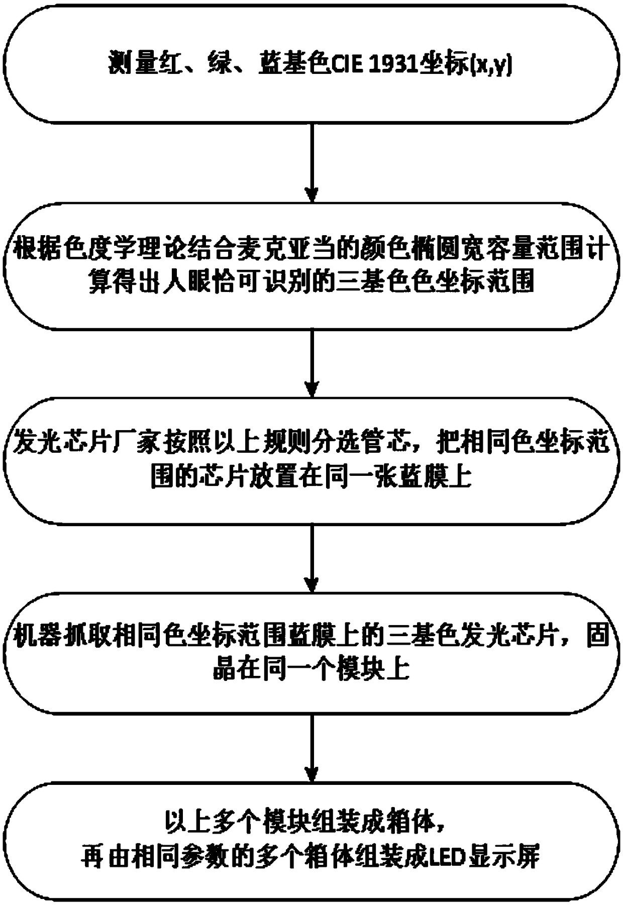
[0040] Red, green, and blue are all displays made of light-emitting chips within one gear (that is, within the same CIE 1931 color coordinate range). The gear division principle is determined by theoretical calculation combined with the actual human eye evaluation effect. This embodiment gear range is selected as: R(δx)=0.0035, R(δy)=0.0025; G(δx)=0.0060, G(δy)=0.0130; B(δx)=0.0025, B(δy)= 0.0020, the designated gear can be appropriately reduced according to the accuracy of the manufacturer's equipment, not limited to the above description. For example: R(δx)=0.0030, R(δy)=0.0020; G(δx)=0.0040, G(δy)=0.0100; B(δx)=0.0020, B(δy)0.0020

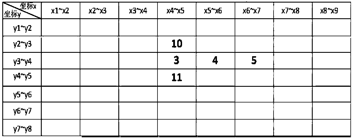
[0041] Manufacturers of green light, blue light, and red light-emitting chips test and classify light-emitting chips according to the stalls shown in Table 2, Table 3, and Table 4 respectively. The test data of a single light-emitting chip in Table 2 falls in which box in the table, which gear it belongs to. When the array module is in the so...

Embodiment 2

[0043] Red and green use light-emitting chips in one gear (that is, within the same CIE 1931 color coordinate range), and blue uses a display made of multiple light-emitting chips in adjacent gears. This embodiment gear range is selected as: R(δx)=0.0030, R(δy)=0.0020; G(δx)=0.0040, G(δy)=0.0100; B(δx)=0.0020, B(δy)= 0.0015

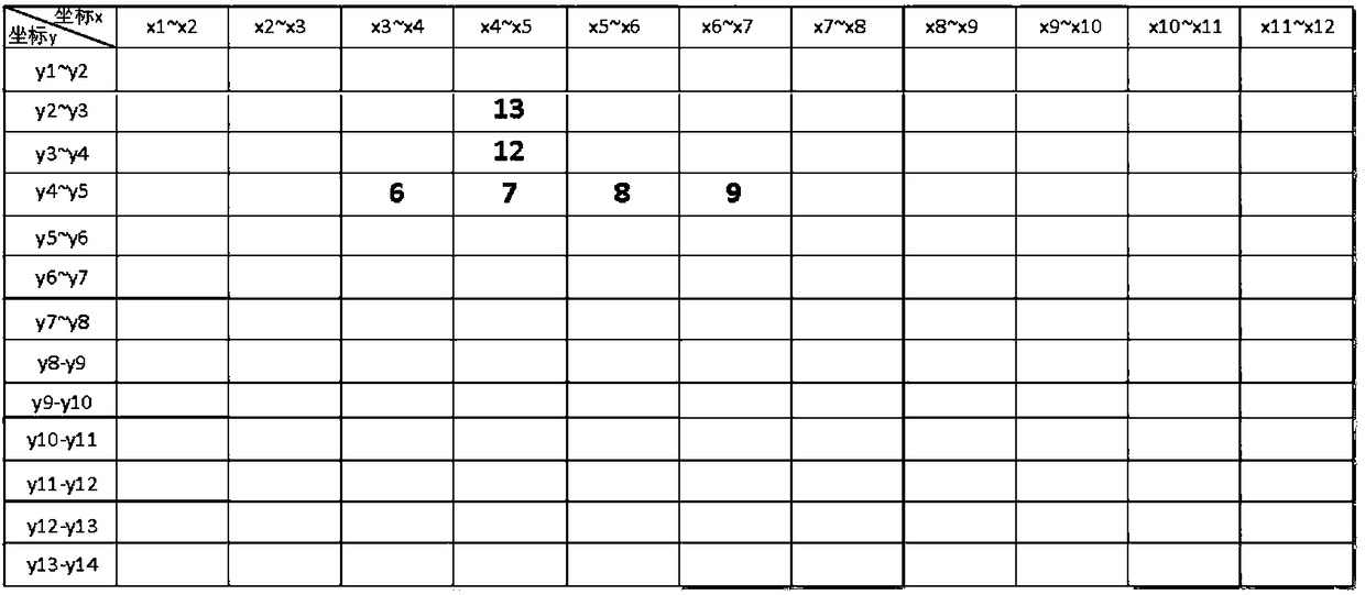
[0044] Manufacturers of green, blue, and red light-emitting chips test and classify light-emitting chips according to the gears shown in Table 2, Table 3, and Table 4. The test data of a single light-emitting chip falls in which box in the table, which gear it belongs to. During the crystal bonding operation, red and green select a light-emitting chip in a box, and blue selects n (1

Embodiment 3

[0046] Red and blue use one gear light-emitting chip (that is, within the same CIE 1931 color coordinate range), and green uses a display made of multiple adjacent gear light-emitting chips. This embodiment gear range is selected as: R(δx)=0.0035, R(δy)=0.0025; G(δx)=0.0060, G(δy)=0.0130; B(δx)=0.0025, B(δy)= 0.0020.

[0047] Manufacturers of green, blue, and red light-emitting chips test and classify light-emitting chips according to the gears shown in Table 2, Table 3, and Table 4. The test data of a single light-emitting chip falls in which box in the table, which gear it belongs to. During the crystal bonding operation, red and blue select a light-emitting chip in a box, and green selects n (1


PUM


Abstract

The invention relates to a color-difference-eliminating light-emitting chip grading method and application method of graded light-emitting chips. The light-emitting chip grading method comprises the steps of: testing CIE1931 color coordinates of an LED light-emitting chip; determining the CIE1931 color coordinate range of the three primary colors of red, green and blue which human eyes can recognize according to MacAdam color ellipse tolerance range in the chromaticity theory and screen display effect and determining grades according to the range R (Delta x, Delta y), G (Delta x, Delta y), B (Delta x, Delta y). The application method of the light-emitting chip in each grade is as follows: the LED display screen is made by using the light-emitting chip belonging to the same grade or the light-emitting chip with increasing or decreasing grades. The invention can eliminate the color difference of the COB packaged display screen or make the color of the display screen gradually change, thereby increasing the comfort of viewing by human eyes.

Description

technical field [0001] The invention belongs to the technical field of LED flat panel display, and in particular relates to a grading method of light-emitting chips for eliminating color differences of COB integrated package display screens and an application method of the grading light-emitting chips. Background technique [0002] With the rapid increase of LED small-pitch LED display market penetration in studios, security monitoring, traffic command centers, large video conference rooms and other professional display markets, the market size of LED small-pitch display screens below P2 (dot pitch 2mm) has remained stable in recent years. rapid growth. At present, the mainstream technology of LED small-pitch display adopts SMD discrete device technology. This technology gradually exposes its technical bottlenecks and limitations in the application process of LED displays, mainly including: reliability and stability issues, and limitations of dot spacing. , fragile protecti...

Claims


Application Information

Patent Timeline
IPC IPC(8): H01L21/66
CPCH01L22/24
Inventor 苗静陈宇程宏斌毛新越丁铁夫
Owner CHANGCHUN CEDAR ELECTRONICS TECH CO LTD
Why Eureka
Try Eureka