A double wafer flip chip package structure

A flip-chip packaging and dual-chip technology, applied in electrical components, electrical solid-state devices, circuits, etc., can solve problems such as high cost and unfavorable heat dissipation, save energy, reduce chip packaging area, and prevent mutual influence between chips. Effect

Inactive Publication Date: 2018-12-28
上海卓弘微系统科技有限公司
View PDF0 Cites 0 Cited by
  • Summary
  • Abstract
  • Description
  • Claims
  • Application Information

AI Technical Summary

Problems solved by technology

The current stackable flip crystal has been proposed, but this structure has many disadvantages, which is not conducive to heat dissipation, the consumption of materials has not been reduced, and the cost is also high

Method used


Image

  • A double wafer flip chip package structure

Examples


Embodiment

[0024] Embodiment: a double-chip flip-chip package package structure.

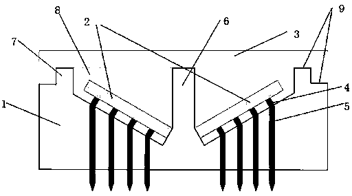
[0025] A double chip flip-chip packaging structure, refer to the attached figure 1 Shown: Including 1. Substrate 2. Chip 3. Heat sink 4. Conductive bump 5. Lead terminal 6. Central partition 7. Substrate top 8. Filler thermal conductive glue 9. Silver glue. It is characterized in that: the substrate 1 is made of insulating material and has a central partition 6, the chip 2 is placed in the slot formed by the central partition 6 and the top 7 of the substrate, and the lead terminal 5 passes through the depression of the 4 conductive bumps and the slope at the bottom of the slot. After melting, the electrical connection is made, and then the thermal conductive glue 8 is injected into the slot to cover the chip to protect the chip and transfer heat. The heat sink 3 is bonded to the central partition 6 and the top of the substrate 7 through silver glue 9 to form a double-chip flip-chip packaging structure.


PUM


Abstract

Based on the flip-chip packaging structure, the invention provides a double wafer flip chip package structure, which is characterized in that the substrate is a substrate with two wafer slots, the substrate is provided with a central separator, the substrate slot has a certain slope, and a plurality of hemispherical grooves are arranged at the contacts of the slot ramps and the chip conductive bumps; the chip has a plurality of cylindrical conductive bumps, and the top of the conductive bumps is hemispherical. An upper heat sink is connected with the top of the substrate. The advantages of thedouble wafer flip chip package structure are: chip soldering self-alignment, double-wafer integrated package, high integration level, chip package area reduction and enhanced heat dissipation function.

Description

technical field [0001] The invention relates to the technical field of semiconductor device packaging, in particular to a double-chip flip-chip packaging structure. Background technique [0002] Flip Chip Interconnect Technology (Flip Chip Interconnect Technology), also known as "inverted chip packaging" or "inverted chip packaging method", is a kind of chip packaging technology. This packaging technology is to arrange the conductive bumps on the active surface of the chip, and flip chip bonding on the substrate, so that the chip can be electrically connected to the substrate through the conductive bumps, and electrically connected to the outside through the internal circuit of the substrate. electronic device. Flip-chip bonding technology is suitable for high-pin-count chip packaging structures, and has the advantages of reducing chip packaging area and shortening signal transmission paths. Flip-chip bonding technology has been widely used in the field of chip packaging. ...

Claims


Application Information

Patent Timeline
Patent Type & Authority Applications(China)
IPC IPC(8): H01L23/31H01L23/367
CPCH01L23/3121H01L23/367H01L23/3672H01L25/04
Inventor 陆宇
Owner 上海卓弘微系统科技有限公司
Why Eureka
Try Eureka