

Cartridge simulation launch test device
A technology for simulating launch and test devices, applied in rocket launch devices, offensive equipment, weapon types, etc., can solve the problems of high test safety hazards, high test costs, low work efficiency, etc., to reduce test costs, ensure product quality, The effect of high work efficiency
Active Publication Date: 2012-10-17
SHANGHAI SPACE PRECISION MACHINERY RES INST
View PDF0 Cites 2 Cited by
- Summary
- Abstract
- Description
- Claims
- Application Information
AI Technical Summary
Problems solved by technology
In order to solve the deficiencies of the existing test device such as low working efficiency, large test safety hazards, and high test cost, the object of the present invention is to provide a simulated launch test device for a bullet. The present invention utilizes Hooke's law and the mechanical tensile The above-mentioned problems are solved, and the technical guarantee of the simulation test is provided for the rapid design and finalization of the missile and the launching tube.
Method used
View moreImage
Smart ImageViewing Examples

Examples
Embodiment Construction
Login to View More PUM
 Abstract
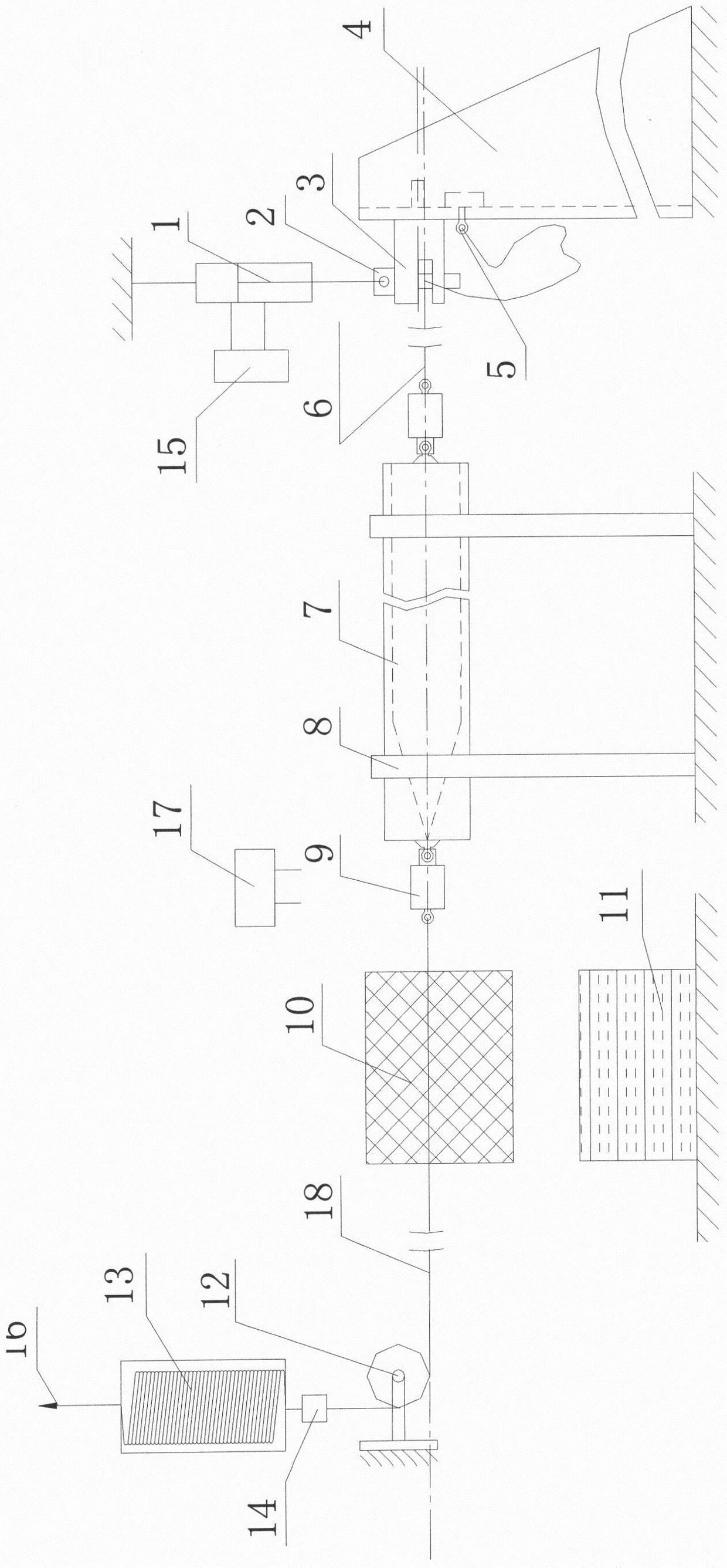
The present invention relates to a simulated launch test device for a missile cartridge, comprising: a tripod [4], on which a double-ear clamp [3] is equipped with a release pin [2]; ], the actuator [1] is connected with the hydraulic loading system [15], and the lower end is fixed on the double-ear chuck [3] with one end of the fiber braided rope [6]; the release pin [2] passes through the fiber braided rope [6] ] and the swivel joint [9] are connected with the tail of the missile to be tested in the missile and the launching tube [7]; The sensor [14] is connected with the spring; the other end of the spring is connected with the vehicle [16]; the speed measurement system [17] is installed directly above the front of the launch tube. The invention solves the problems of barrel coordination, missile trajectory measurement and verification, etc., and achieves the beneficial effects of shortening the development cycle, reducing test risk, and improving test safety and test accuracy.
Description
technical field The invention relates to a test device for missile launching equipment, in particular to a test device for simulating and evaluating the launching dynamic mechanical characteristics of missiles and launch tubes. Background technique In the past, solid gunpowder was used as a booster in the barrel launch test, and the launch speed was changed by adjusting the amount of gunpowder and the filling method, verifying the coordination of the barrel, measuring the trajectory of the missile, the force of the launcher and the number of times of use. At present, the known barrel launch test device mainly uses solid gunpowder as the power for the test. Although there is no problem with the authenticity of the simulation, there is a risk that the job site is dangerous when the engine is ignited, and the stability and repeatability of each charge are very poor. Moreover, the high requirements for the test site have brought certain difficulties to the improved design and d...
Claims
Login to View More Application Information
Patent Timeline
 Patent Type & AuthorityPatents(China)
IPC IPC(8): F41F3/04
Inventor周改超陆国民王海东
OwnerSHANGHAI SPACE PRECISION MACHINERY RES INST