Tool connecting structure

A connection structure and cutting tool technology, applied in the direction of manufacturing tools, bonding grinding wheels, using vibrating fluid, etc., can solve problems such as cost increase, scratches, and impact on the service life of the cutter body, to ensure processing quality and buffer cutting collisions Effect

Pending Publication Date: 2019-01-01
CONPROFE TECH GRP CO LTD +1
View PDF0 Cites 4 Cited by
  • Summary
  • Abstract
  • Description
  • Claims
  • Application Information

AI Technical Summary

Problems solved by technology

[0003] The grinding tool is connected to the tool handle. In the prior art, when the tool handle is connected to the cutter head body, the concentricity between the tool handle and the cutter head body cannot be guaranteed, resulting in end face runout and circumferential runout of the cutter head body, which will cause irregularities on the surface of the workpiece. If it is flat or scratched, it will also affect the service life of the cutter head body, resulting in an increase in cost
[0004] To sum up, in the existing grinding tools, the cutterhead body and the horn of the tool handle are not concentric, which will cause uneven or scratched workpiece surfaces, and will also affect the service life of the cutterhead body

Method used


Image

  • Tool connecting structure
  • Tool connecting structure
  • Tool connecting structure

Examples


Embodiment Construction

[0035] The technical solutions of the present invention will be clearly and completely described below in conjunction with the accompanying drawings. Apparently, the described embodiments are some of the embodiments of the present invention, but not all of them. Based on the embodiments of the present invention, all other embodiments obtained by persons of ordinary skill in the art without making creative efforts belong to the protection scope of the present invention. It should be noted that, in the case of no conflict, the embodiments of the present application and the features in the embodiments can be combined with each other.

[0036] The present invention will be further explained below in combination with specific embodiments.

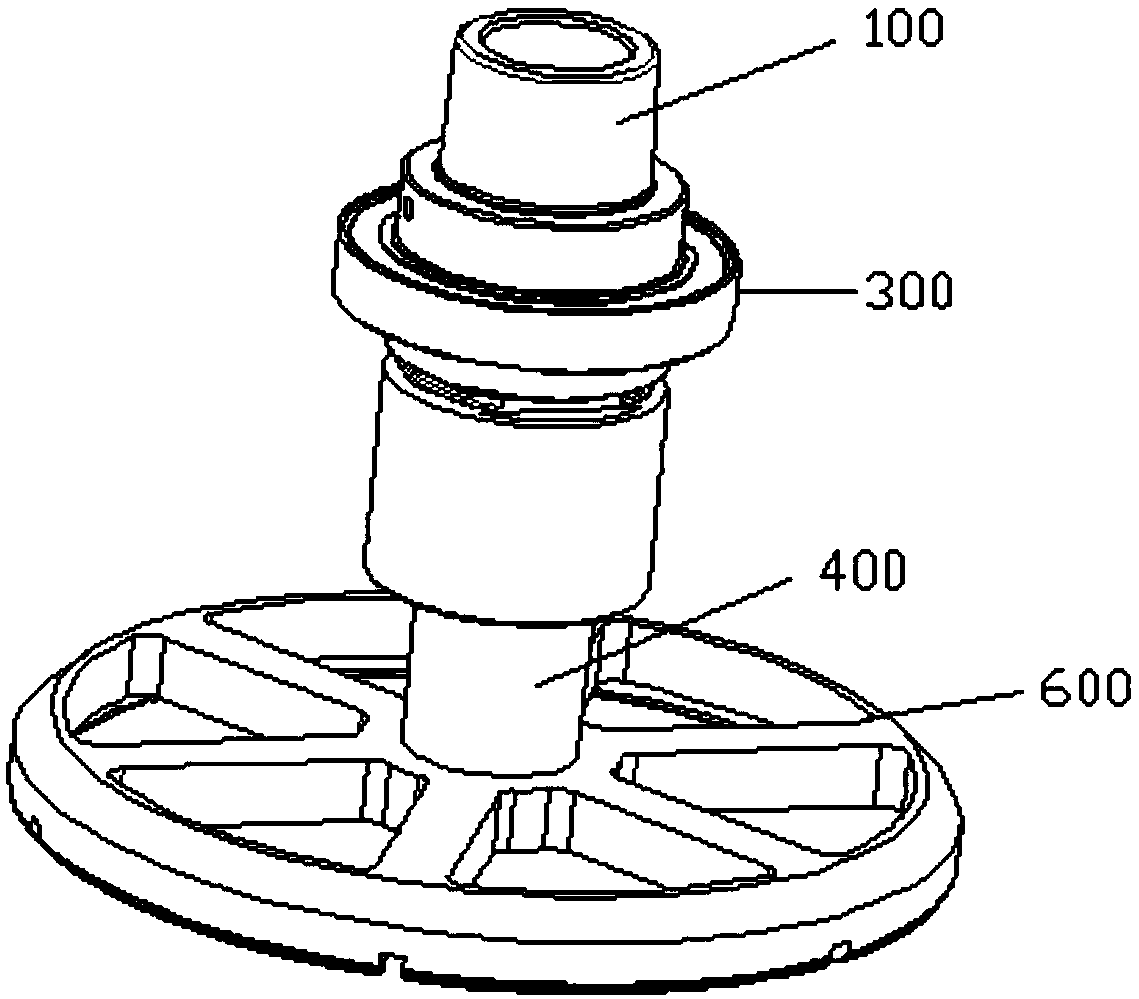
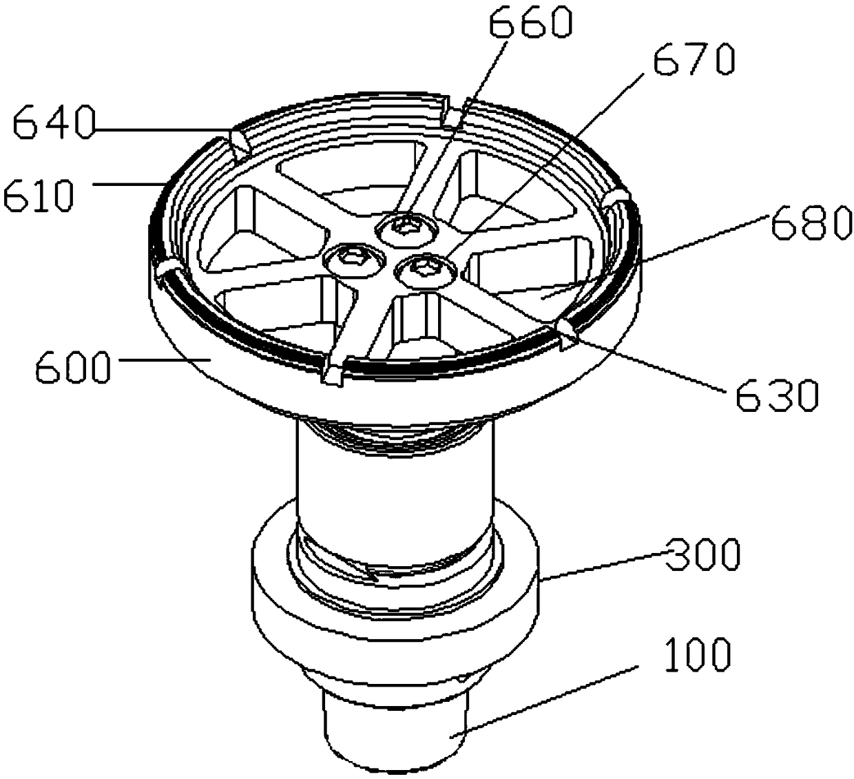
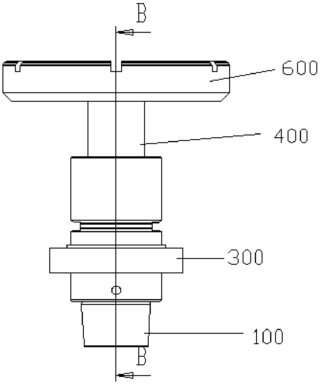
[0037] refer to Figure 1 to Figure 7 , the tool connection structure provided by the embodiment of the present invention includes:

[0038] Ultrasonic cutter body 100, the first end of which is used to connect with the spindle of the machine ...


PUM


Abstract

The invention provides a tool connecting structure, and relates to the technical field of machining. The tool connecting structure comprises an ultrasonic tool body, a wireless transmission and receiving device, an ultrasonic transducer and a grinding tool. The ultrasonic transducer comprises an amplitude-change pole and a piezoelectric vibrator. The piezoelectric vibrator is connected with the wireless transmission and receiving device. A connecting protrusion connected with the grinding tool and multiple second locking holes arranged in the peripheral side of the connecting protrusion are arranged on the bottom face of the second end of the amplitude-change pole. The first end of the amplitude-change pole is connected with the second end of the ultrasonic tool body through a connecting part. The grinding tool comprises a tool disc body, a connecting hole used for being connected with the amplitude-change pole is formed in the middle of the grinding tool, and multiple first locking holes corresponding to the positions of the second locking holes are formed in the circumferential direction of the connecting hole. A grinding portion is arranged at one end of the tool disc body. At least one chip removal groove is formed on the grinding portion, and a cutting edge is formed on a groove opening of each chip removal groove. The tool connecting structure has the advantages of beinghigh in machining precision and long in service life.

Description

technical field [0001] The invention relates to the technical field of machining, in particular to a tool connection structure. Background technique [0002] The current grinding tool usually includes a cutterhead body and a grinding part located at one end of the cutterhead body. The grinding tool is driven to rotate through a rotating shaft by a driving device, and the workpiece surface is ground by the grinding part. However, the current grinding tools still have the following problems: [0003] The grinding tool is connected to the tool handle. In the prior art, when the tool handle is connected to the cutter head body, the concentricity between the tool handle and the cutter head body cannot be guaranteed, resulting in end face runout and circumferential runout of the cutter head body, which will cause irregularities on the surface of the workpiece. If it is flat or has scratches, it will also affect the service life of the cutterhead body, resulting in an increase in ...

Claims


Application Information

Patent Timeline
Patent Type & Authority Applications(China)
IPC IPC(8): B24B41/047B24B45/00B24B1/04B24D7/10B24D7/00B06B1/06B06B3/02
CPCB24B41/0475B06B1/06B06B3/02B24B1/04B24B41/047B24B45/006B24D7/00B24D7/10
Inventor 颜炳姜李伟秋林一松
Owner CONPROFE TECH GRP CO LTD
Why Eureka
Try Eureka