Two-dimensional precise anti-backlash adjusting mechanism of photoelectric autocollimator

A photoelectric autocollimator and adjustment mechanism technology, applied in the direction of supporting machines, mechanical equipment, machine/stands, etc., can solve the problems of moving out of the measurement range, jumping and empty distance, and high measurement accuracy, avoiding measurement data coupling, Easy to install and operate, improve the effect of adjustment efficiency

Pending Publication Date: 2022-03-25
BEIJING AEROSPACE INST FOR METROLOGY & MEASUREMENT TECH
View PDF4 Cites 0 Cited by
  • Summary
  • Abstract
  • Description
  • Claims
  • Application Information

AI Technical Summary

Problems solved by technology

During the adjustment process, due to the small angle range and high measurement accuracy, after a large-scale adjustment, it is necessary to use a precision adjustment base to fine-tune the photoelectric autocollimator within a small angle range. The existing adjustment base generally adopts a three-layer board method , the bottom layer is used as a fixed base, one of the other two layers is used for azimuth adjustment, and the other layer is used for pitch adjustment. The structure is relatively complicated
The existing adjustment base generally uses the screw top column as the adjustment top column, and the azimuth adjustment is to adjust the photoelectric autocollimator connecting plate through the way of the left and right screw top columns facing each other, and the operator needs to adjust the left and right screw top columns respectively. Rotation operation, jumping and empty travel will occur during the operation, resulting in sudden changes in the measurement data of the photoelectric autocollimator, or even moving out of the measurement range. For pitch adjustment, the method of jacking up the screw top column is adopted, and the knob protrudes from the base. , which brings inconvenience to the installation and operation of the photoelectric autocollimator

Method used


Image

  • Two-dimensional precise anti-backlash adjusting mechanism of photoelectric autocollimator
  • Two-dimensional precise anti-backlash adjusting mechanism of photoelectric autocollimator
  • Two-dimensional precise anti-backlash adjusting mechanism of photoelectric autocollimator

Examples


Embodiment Construction

[0036] The present invention will be described in detail below with reference to the accompanying drawings and examples.

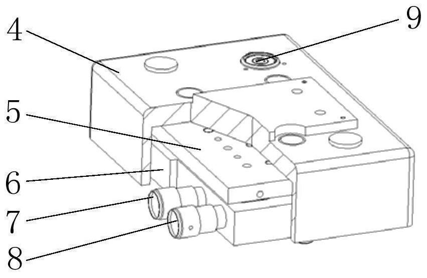
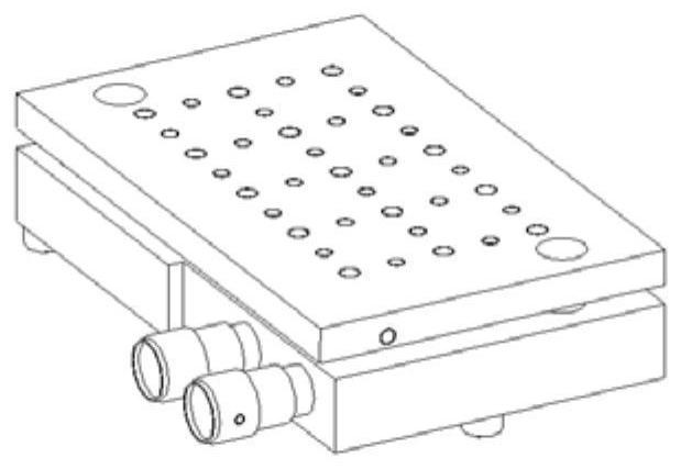
[0037] This embodiment provides a photoelectric autocollimator two-dimensional precision anti-backlash adjustment mechanism, see the attached Figure 1-2 , the adjustment mechanism 3 includes: an upper plate 5, a lower plate 6, a rotating shaft 28, a top column 29, a pressure cap 31, an azimuth component, a pitch component, an anti-backlash component, an adapter seat 4 and a level 9;

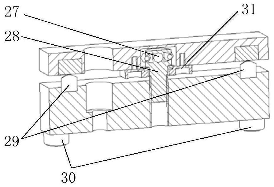
[0038] See attached image 3 , the lower surface of the lower plate 6 is provided with a bottom foot 30 for supporting on the external platform, and the upper surface of the lower plate 6 is fixed with two top posts 29, and the upper ends of the top posts 29 are processed as arc surfaces; The upper plate 5 is placed on the lower plate 6 and supported on the top column 29, that is, the lower surface of the upper plate 5 is in contact with the arc surface of the top column 29...


PUM


Abstract

The invention discloses a two-dimensional precise anti-backlash adjusting mechanism for a photoelectric autocollimator. The two-dimensional precise anti-backlash adjusting mechanism comprises an upper-layer plate, a lower-layer plate, a rotating shaft, a top column, an orientation assembly, a pitching assembly and an anti-backlash assembly, two support pillars are fixed on the upper surface of the lower layer plate; the upper-layer plate is placed on the lower-layer plate and is supported on the support pillars; the rotating shaft is a stepped shaft, the small-diameter section of the rotating shaft is mounted in the lower-layer plate, and the large-diameter section of the rotating shaft is mounted in a mounting hole formed in the upper-layer plate; the rotating shaft is located between the two jacking columns. The orientation assembly, the pitching assembly and the gap eliminating assembly are all installed between the upper layer plate and the lower layer plate. The orientation assembly is used for driving the upper-layer plate to perform orientation rotation relative to the lower-layer plate by taking the rotating shaft as a rotating shaft; the pitching assembly is used for driving the upper-layer plate to conduct pitching rotation relative to the lower-layer plate with the upper end of the top column as a rotation supporting point. The gap eliminating assembly is used for eliminating gaps between parts in the adjusting mechanism. The device is simple in structure and reliable in adjustment, and can overcome the problem that the measurement data of the photoelectric auto-collimator is suddenly changed and moved out of the measurement range.

Description

technical field [0001] The invention belongs to the technical field of precision measurement, and in particular relates to a two-dimensional precise anti-backlash adjustment mechanism of a photoelectric autocollimator. Background technique [0002] The photoelectric autocollimator adopts the principle of autocollimation angle measurement in geometric optics. The scattered light emitted by the light source is projected onto the reticle at the focal plane of the collimating optical system after passing through the condenser, and then exits in parallel after passing through the collimating optical system. The optical signal of the information is reflected back to the collimation optical system, deflected by the beam splitter, and focused and imaged on the CMOS image sensor. The centroid coordinates of the image points are extracted by means of image processing, and converted into angle information through geometric optics. [0003] Photoelectric autocollimator is a precision ...

Claims


Application Information

Patent Timeline
Patent Type & Authority Applications(China)
IPC IPC(8): F16M11/10F16M11/08F16M11/18
CPCF16M11/10F16M11/08F16M11/18
Inventor 李永刚王春喜汪涛刘书君刘岩张忠武吴跃沙春哲王蕾赵功伟
Owner BEIJING AEROSPACE INST FOR METROLOGY & MEASUREMENT TECH
Why Eureka
Try Eureka