Outside-cabinet auxiliary guide rail device for floor type circuit breaker of switch cabinet

A cabinet floor-mounted, auxiliary guide rail technology, applied in switchgear, electrical components and other directions, can solve the problem of not adapting to installation sites of different heights, and achieve the effect of reducing construction costs, ensuring support strength, and facilitating assembly, disassembly and connection.

Active Publication Date: 2021-06-11
TIANJIN PINGGAO INTELLIGENT ELECTRIC +2
View PDF8 Cites 0 Cited by
  • Summary
  • Abstract
  • Description
  • Claims
  • Application Information

AI Technical Summary

Problems solved by technology

[0005] The purpose of the present invention is to provide an auxiliary guide rail device outside the cabinet for floor-standing circuit breakers in switch cabinets, so as to solve the technical problem in the prior art that the height of the handcart ramp is fixed and not suitable for installation places with different heights

Method used


Image

  • Outside-cabinet auxiliary guide rail device for floor type circuit breaker of switch cabinet
  • Outside-cabinet auxiliary guide rail device for floor type circuit breaker of switch cabinet
  • Outside-cabinet auxiliary guide rail device for floor type circuit breaker of switch cabinet

Examples


specific Embodiment 1

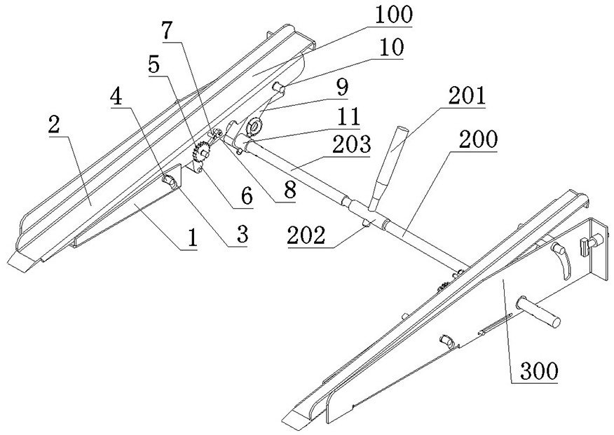
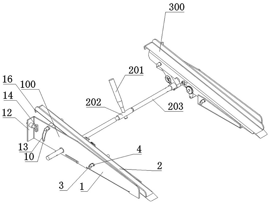
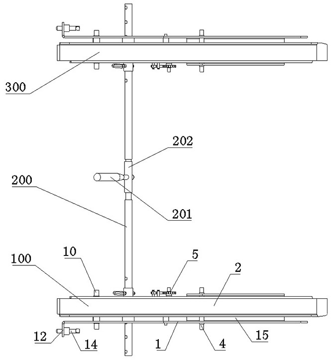
[0055] like Figure 1 to Figure 15 As shown, in this embodiment, the structure of the auxiliary guide rail device outside the cabinet for the floor-standing circuit breaker of the switch cabinet includes three parts: the left guide rail assembly 100, the right guide rail assembly 300 and the middle span assembly 200. These three parts are detachably assembled together , The guide rail assembly on both sides and the middle span assembly 200 can be disassembled as independent modules, which is convenient for transportation and portability, and is also convenient for assembly and molding.

[0056] The middle span assembly 200 here can conveniently adjust the span of the guide rail assembly on both sides to meet the requirements of different types of floor-mounted circuit breakers and improve the versatility. like Figure 15 As shown, the middle span assembly 200 specifically includes connecting rods 203 on both sides, and the connecting rods 203 on both sides are assembled toget...

specific Embodiment 2

[0074] The difference between it and Embodiment 1 mainly lies in that in Embodiment 1, the assembly of the middle span is adjustable. In this embodiment, while retaining the adjustable slope of the guide rails on both sides, a fixed-length intermediate span can also be used. In this case, only a single-width circuit breaker type can be used.

specific Embodiment 3

[0076] The main difference between it and Embodiment 1 is that in Embodiment 1, a middle span assembly is detachably installed between the guide rail assemblies on both sides, which can effectively improve the strength of the entire guide rail device. In this embodiment, if only relying on the assembly strength of the guide rails on both sides to meet the support strength requirements of the circuit breaker, the assembly in the middle span can also be omitted. At this time, the assembly positions of the guide rails on both sides can be arranged arbitrarily according to the actual span.


PUM


Abstract

The invention relates to an outside-cabinet auxiliary guide rail device for a floor type circuit breaker of a switch cabinet, and the device comprises guide rail assemblies at two sides, which are distributed at intervals in the left-right direction, and are used in cooperation to provide slope support, thereby guiding the floor type circuit breaker to climb forward to enter the switch cabinet; the guide rail assembly on each side comprises a base used for being supported on a corresponding fixed foundation; and a guide rail plate which extends along the front-back direction and is used for supporting and guiding the floor type circuit breaker; wherein the guide rail plate is installed on the base in a pitching adjustable mode along an arc path so that the height of the guide rail plate can be adjusted according to actual needs. The guide rail plate is installed on the corresponding base in a pitching adjustable mode along the arc path, the guide rail plate can be adjusted to the proper height according to the actual height requirement, then the assembly requirements of installation places with different heights can be conveniently met, the assembly precision requirement for the installation position height can be effectively lowered, and the site construction cost is lowered.

Description

technical field [0001] The invention belongs to the technical field of pulling mechanisms applied to handcarts, and in particular relates to an auxiliary guide rail device outside the cabinet for a floor-standing circuit breaker of a switch cabinet. Background technique [0002] In medium-voltage switchgear, armored removable switchgear is a mainstream product, and its circuit breaker is a movable part that can be moved out of the cabinet as a separate component for isolation and maintenance and replacement. According to the layout position of the circuit breaker, it can be divided into central type and floor type. The central type circuit breaker is located in the middle of the switchgear product, and it needs to be equipped with a transfer platform to transfer and assist in the operation of entering the cabinet. Relatively speaking, the floor-mounted circuit breaker is installed at the bottom of the switch cabinet and has its own wheels. It does not need a transfer platfor...

Claims


Application Information

Patent Timeline
Patent Type & Authority Applications(China)
IPC IPC(8): H02B3/00
CPCH02B3/00
Inventor 张罗锐张敬涛侯小默杜敬敬王茜姚锋娟齐婵焦淑敏
Owner TIANJIN PINGGAO INTELLIGENT ELECTRIC
Why Eureka
Try Eureka