On-position type gas analysis system with on-position calibration function

A technology of gas analysis system and gas pipeline, which is applied in the direction of material analysis, material analysis by optical means, and measurement device, etc., which can solve the problems of complex device, difficult installation and debugging, high processing and installation precision, and achieve simple device, Reliable calibration results and low assembly accuracy requirements

Active Publication Date: 2011-06-15
FOCUSED PHOTONICS
View PDF1 Cites 8 Cited by
  • Summary
  • Abstract
  • Description
  • Claims
  • Application Information

AI Technical Summary

Problems solved by technology

[0009] The invention provides an on-site gas analysis system with an on-site calibration function, which overcomes the shortcomings of the existing on-site gas analysis system with an on-site calibration function, such as complex devices, high processing and installation precision requirements, and difficult installation and debugging.

Method used


Image

  • On-position type gas analysis system with on-position calibration function
  • On-position type gas analysis system with on-position calibration function

Examples


Embodiment

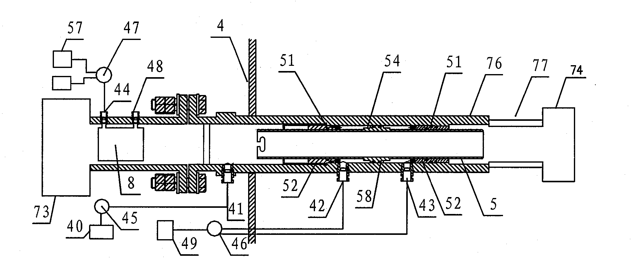
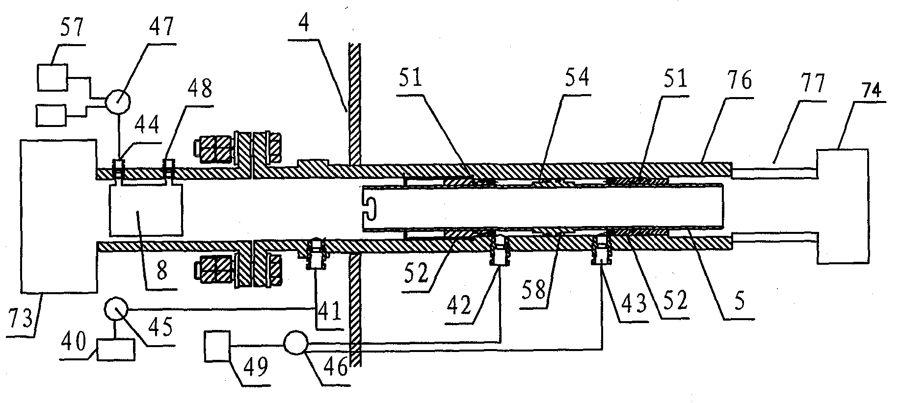
[0019] Such as figure 1 As shown, an on-site gas analysis system with an on-site calibration function is a non-dispersive infrared spectroscopy (NDIR) gas analysis system, including a light emitting and receiving device 73 and a measuring probe 76 . The light emitting and receiving device 73 is connected to the measuring probe 76 through a flange and installed on the measured gas pipeline 4. The light return device 74 is installed on the end face of the measuring probe 76, and a gap 77 is provided on the measuring probe 76 for the measured gas pipeline 4. Process gas passes through. The gas analysis system also includes additional pipes and control devices.

[0020] The additional pipe is the telescopic pipe 5 installed inside the measuring probe 76 , the cross section of the telescopic pipe is circular, and the ventilation joint 41 is installed on the measuring probe 76 .

[0021] The control device is as follows: the detachable end block 52 is installed on the inner wall o...


PUM


Abstract

The invention discloses an in situ gas analysis system with an in situ calibration function, which includes a light emitting device, a light receiving device, a signal analysis device, a mechanical connection structure and a measuring probe, wherein, the light emitting device and the light receiving device is combined with a measured gas pipeline through the mechanical connection structure, and also includes an attached tube, a control device and a gas replacement device; the attached tube moveablely sleeves on the measuring probe, the extension end of the attached tube and the measuring probe are matched with each other in a measured gas pipeline and on a measured optical path to form a closed pipeline which is isolated from the measured gas, the gas analysis system can be in calibrationor measurement situation caused by the extension or the retraction of the attached tube, the control device is used to control the attached tube and the measuring probe to form the closed pipeline which is isolated from the measured gas, the gas replacement device comprising a gas source with a known concentration, a valve and a ventilation joint communicates with the closed pipeline.

Description

[0001] The patent of the present invention is a divisional application of the Chinese patent application number 2005100607797. The filing date of the original application is September 15, 2005, and the title of the invention is "an on-site gas analysis system with an on-site calibration function". technical field [0002] The invention relates to an on-site gas analysis system, in particular to an on-site gas analysis system with an on-site calibration function. Background technique [0003] The on-site gas analysis system is different from the traditional sampling method gas analysis system. It does not require sampling and pretreatment process, overcomes many defects of the traditional sampling method gas analysis system, and has the advantages of simple system, high reliability, fast measurement response speed, and analysis It has the advantages of high precision, can measure the concentration and speed of gas, and has been widely used in modern industry, scientific resear...

Claims


Application Information

Patent Timeline
Patent Type & Authority Patents(China)
IPC IPC(8): G01N21/53G01N21/31G01N21/01G01N21/27
Inventor 王健熊志才钟安平
Owner FOCUSED PHOTONICS
Why Eureka
Try Eureka