Pneumatic brake motor and pneumatic brake method

A technology of pneumatic brake and electric motor, which is applied in the direction of electric components, mechanical energy control, brake type, etc., can solve the problems of high assembly precision, large rectifier power consumption, rectifier burnout, etc., and achieve low assembly precision and low manufacturing cost , The effect of adjustable braking force

Active Publication Date: 2009-06-03
HANGZHOU XIANGSHENG ABRASIVE MACHINE MFG
View PDF0 Cites 7 Cited by
  • Summary
  • Abstract
  • Description
  • Claims
  • Application Information

AI Technical Summary

Problems solved by technology

[0002] In terms of structural design, the existing electromagnetic braking motor braking module adopts the electromagnet action structure, so the coil in the electromagnet will inevitably generate heat and generate heat, and the rectifier will also generate heat when it works, and the power consumption is large, and the rectifier often burns out , coil short circuit and other faults; secondly, high assembly precision requirements and high manufacturing costs

Method used


Image

  • Pneumatic brake motor and pneumatic brake method
  • Pneumatic brake motor and pneumatic brake method

Examples


Embodiment 1

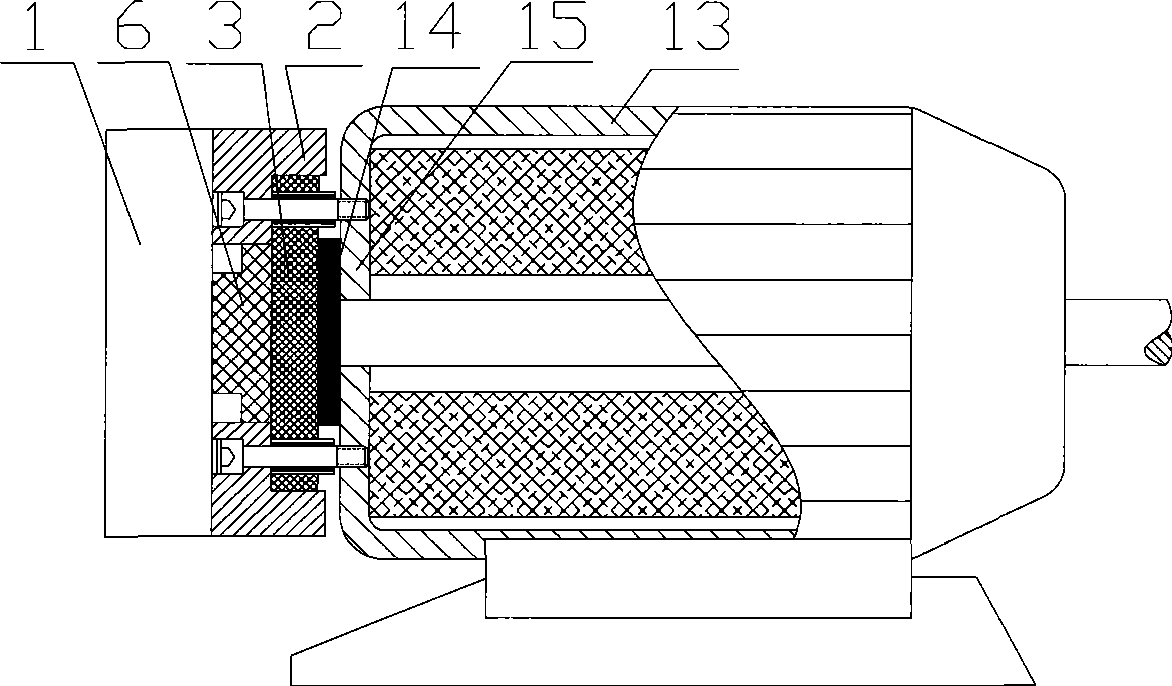
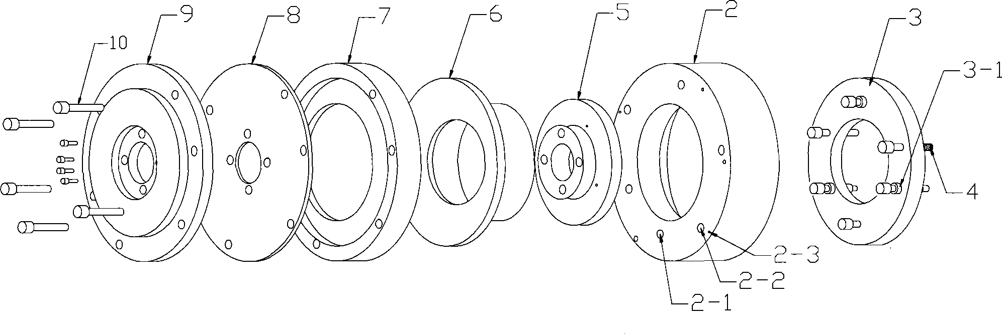
[0010] Embodiment 1: with reference to attached figure 1 and 2 . Pneumatic brake motor, the brake pad 3 is located in the groove on one side of the base 2 and the braking surface of the brake pad 3 and the friction pad 14 in the motor 13 form a brake brake cooperation, the end face of the base 2 and the end face 15 of the motor 13 The other side of the base 2 is connected to the brake cylinder 1 and the piston 6 in the brake cylinder 1 pushes the brake pad 3 to brake. There are 3 or more base countersunk bolt holes on the brake pad 3, and the movable sliding sleeve 3-1 is located in the hole of the brake pad 3 and uses the connecting screw of the base 2 and the motor as a sliding column to form a joint with the brake pad 3. Sliding fit; the base 2 is equipped with 3 or more return spring positioning bolts 2-1 and corresponds to 3 or more through holes on the brake pad 3, and the bolt rods of 3 or more bolts pass through the brake The through hole of the plate 3, the bolt ro...

Embodiment 2

[0011] Embodiment 2: On the basis of Embodiment 1, the brake cylinder 1 is composed of a film cylinder base 9, a film 8, an outer ring flange 7, a piston 6, an inner ring flange 5, a brake pad 3 and one end surface of the base 2 The film 8 is located in the cavity formed by the film cylinder base 9, the outer ring flange 7 and the inner ring flange 5, the piston 6 is located between the outer ring flange 7 and the inner ring flange 5, the inner ring flange 5, the outer ring flange Ring flange 7, film 8 and film cylinder base 9 form a hollow shaft film cylinder through bolts 10 and 11. An annular sealed cavity is formed between them, and the air inlet 12 is arranged on the film cylinder base 9 and is communicated with the air outlet of the compressed air.

Embodiment 3

[0012] Embodiment 3: On the basis of Embodiment 1, the brake cylinder 1 can adopt an electric cylinder, and the structure of the electric cylinder belongs to the prior art, and will not be described here.


PUM


Abstract

The invention relates to a pneumatic brake motor and a pneumatic brake method of a pneumatic brake motor friction plate. When compressed air is filled into a brake cylinder through an air inlet hole in the brake cylinder, a piston in the brake cylinder pushes a brake plate to press the friction plate in the motor and completes the brake action; when the compressed air is released, the piston in the brake cylinder is reset, and the brake plate is reset under the action of a return spring, thereby completing one brake action. The invention has the advantages that: firstly, the invention does not use electricity and generates no heating; secondly, the structure is simple, the brake is reliable and the braking force is adjustable; thirdly, the manufacturing cost is low, the assembly precision requirement is low and the invention has no faults basically.

Description

technical field [0001] The invention relates to a pneumatic brake motor and a pneumatic brake method for a friction plate of the pneumatic brake motor, belonging to the field of pneumatic brake module manufacturing. Background technique [0002] In terms of structural design, the existing electromagnetic braking motor braking module adopts the electromagnet action structure, so the coil in the electromagnet will inevitably generate heat and generate heat, and the rectifier will also generate heat when it works, and the power consumption is large, and the rectifier often burns out , coil short circuit and other faults; secondly, high assembly precision requirements and high manufacturing costs. Contents of the invention [0003] Design purpose: To avoid the deficiencies in the background technology, to design a pneumatic braking motor and a pneumatic braking method using compressed air as a braking source. [0004] Design scheme: In order to achieve the above design purpos...

Claims


Application Information

Patent Timeline
Patent Type & Authority Applications(China)
IPC IPC(8): H02K7/102F16D65/20F16D65/092
Inventor 陈勇奇
Owner HANGZHOU XIANGSHENG ABRASIVE MACHINE MFG
Why Eureka
Try Eureka