Turbine nozzle support structure

a technology of supporting structure and turbine nozzle, which is applied in the direction of machines/engines, liquid fuel engines, lighting and heating apparatus, etc., can solve the problems of difficult use of monolithic turbine nozzles, and achieve low machining accuracy, low assembling accuracy, and effective and surely transmitted

Active Publication Date: 2006-09-26
KAWASAKI HEAVY IND LTD
View PDF5 Cites 8 Cited by
  • Summary
  • Abstract
  • Description
  • Claims
  • Application Information

AI Technical Summary

Benefits of technology

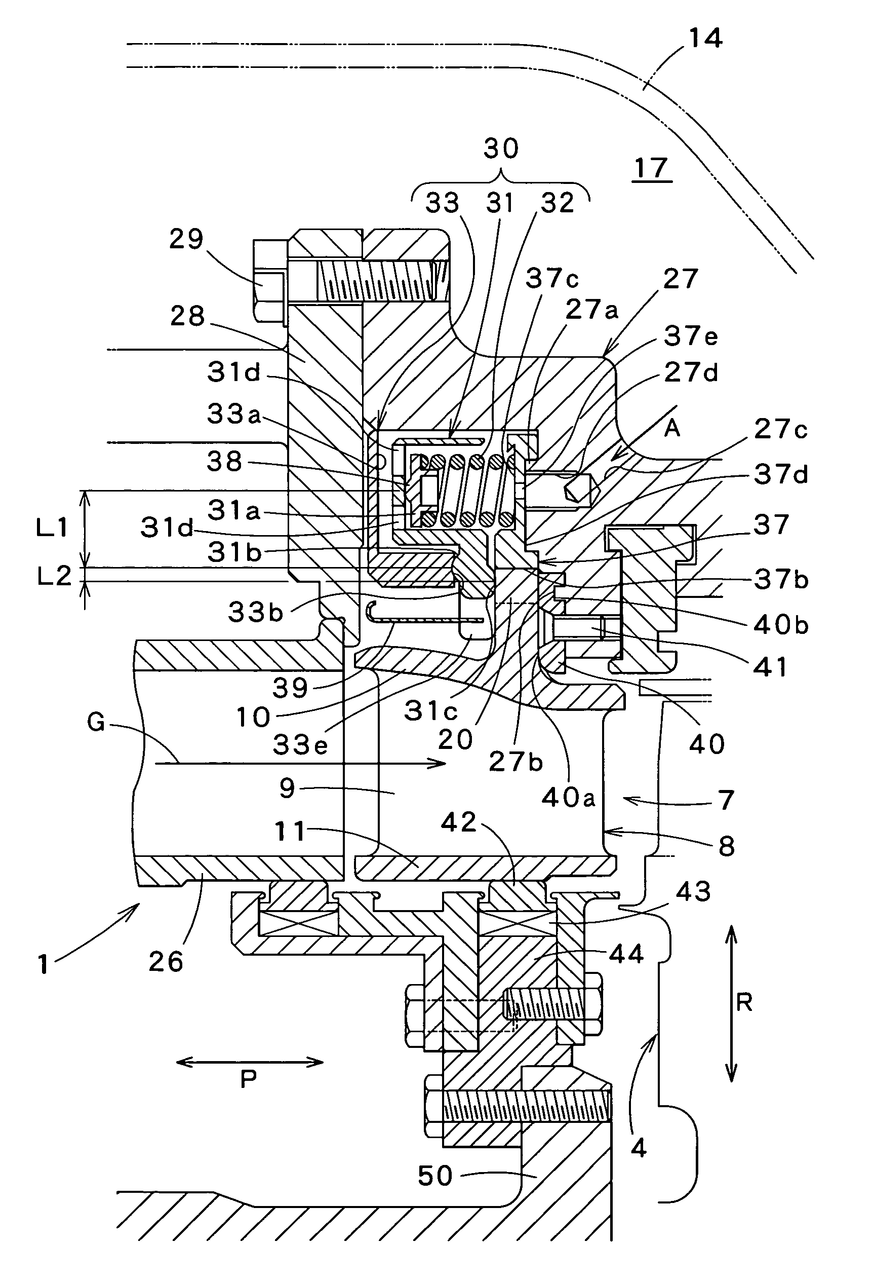
[0011]The force-multiplying mechanism of the turbine nozzle support structure produces a high pressure by multiplying the resilient force of the spring by the ratio of the distance between a point of action of the resilience of the spring on the spring bearing and the fulcrum part to the distance between the supporting point and the pressing part, and presses the flange of the turbine nozzle firmly against the nozzle support by the high pressure. Therefore, the turbine nozzle can be stably supported on the nozzle support by the resilient force of the small spring that can be disposed in a narrow space. Since the turbine nozzle is formed of a ceramic material excellent in heat resistance, a high turbine inlet temperature can be used to operate the gas turbine at high efficiency, to prevent environmental pollution and to extend the life of the gas turbine. Since the difference in thermal expansion between the ceramic turbine nozzle and the adjacent metal support members is absorbed by the spring, the ceramic turbine nozzle is supported axially elastically, and the ceramic turbine nozzle and the metal support member are supported individually, the ceramic turbine nozzle is affected scarcely by the deformation of the metal support member, and the ceramic turbine nozzle is prevented from damaging due to the unconformity of its deformation with that of the metal support member.
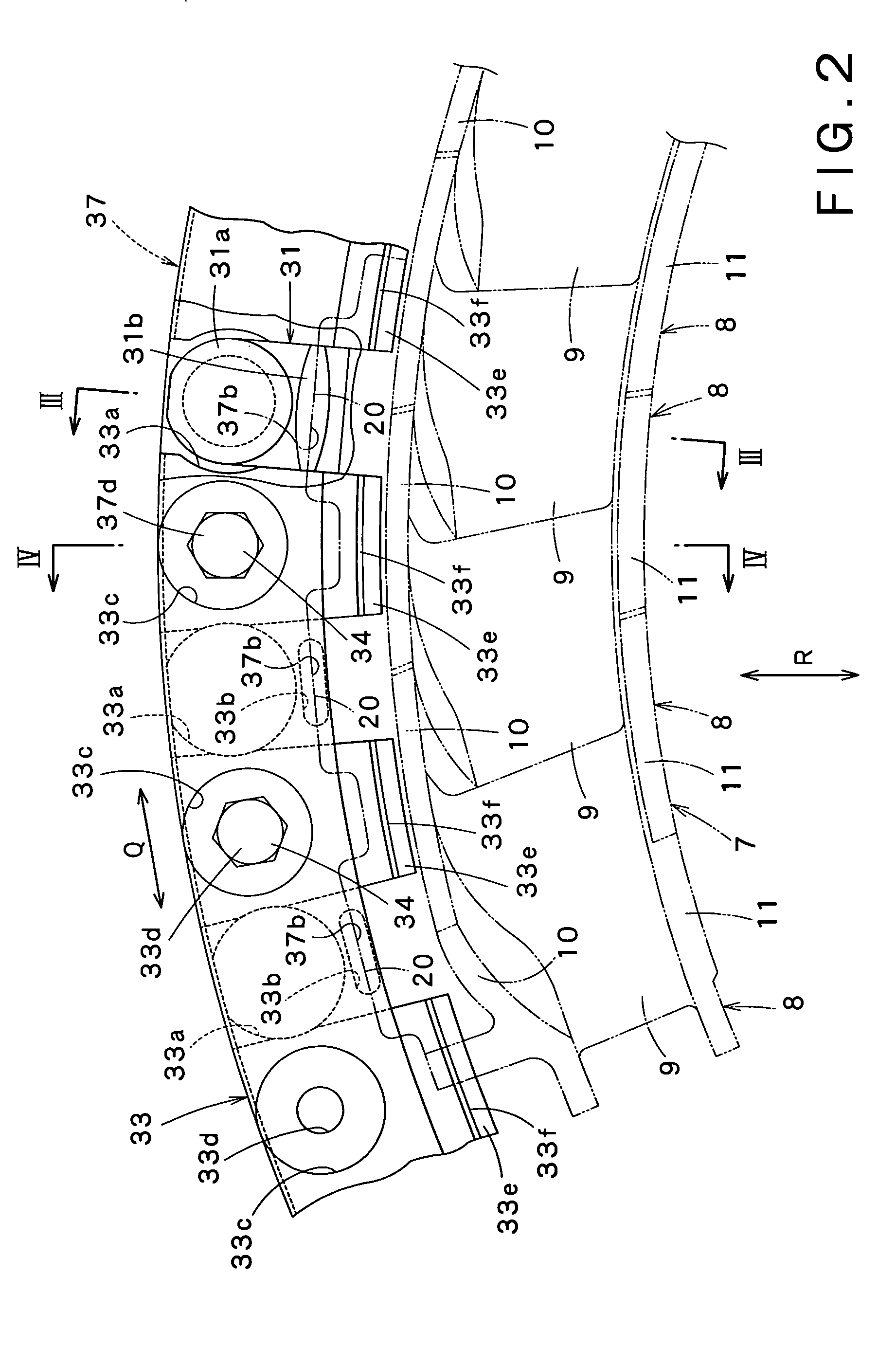
[0014]In the turbine nozzle support structure according to the present invention, it is preferable that either the fulcrum part of the pressing member or the bearing part of the fulcrum supporting member has a spheroidal surface, and the fulcrum part of the pressing member is in point contact with the bearing part of the fulcrum supporting member. Thus, the area of contact between the fulcrum part and the fulcrum supporting member is greater than the area of point contact between a simple spherical surface and a plane, and the degree of freedom of motion of the fulcrum part relative to the fulcrum supporting member is larger than that of members in line-contact with each other. Therefore, the fulcrum part is able to move smoothly on the bearing part of the fulcrum supporting member, the resilient force of the spring can be effectively and surely transmitted to the turbine nozzle by the turning pressing member. Even if the pressing member and the fulcrum supporting member are manufactured in a low machining accuracy and are assembled in a low assembling accuracy, the support part of the slightly tilted pressing member can be brought into contact with the fulcrum supporting member at a predetermined position without trouble.
[0015]In the turbine nozzle support structure according to the present invention, it is preferable that the pressing member is in line contact with the flange of the turbine nozzle. Thus, even if the pressing member is tilted from a normal position, the pressing member in line contact instead of surface contact with the flange will not come into partial contact at the edges with the flange and the point of action of force will not be dislocated and hence the turbine nozzle can be stably pressed against the nozzle support.
[0016]In the turbine nozzle support structure according to the present invention, it is preferable that the nozzle support is provided with an air passage for guiding compressed air supplied from a compressor included in the gas turbine into the force-multiplying mechanisms. Even if a high turbine inlet temperature is used because the ceramic turbine nozzle is used, the pressing member, the spring and the fulcrum supporting member, which are formed of metals, of the force-multiplying mechanisms can be effectively cooled by the compressed air.
[0017]In the turbine nozzle support structure according to the present invention, it is preferable that a heat insulator is interposed between the force-multiplying mechanism and the turbine nozzle. Even if a high turbine inlet temperature is used because the ceramic turbine nozzle is used, the pressing member, the spring and the fulcrum supporting member, which are formed of metals, of the force-multiplying mechanism can be effective shielded from heat radiated from the turbine nozzle by the simple heat insulator.
[0018]The turbine nozzle support structure of the present invention produces a high pressure by multiplying the resilient force of the spring by the force-multiplying mechanism and presses the flange of the turbine nozzle against the nozzle support by the high pressure. Even though the turbine nozzle support structure capable of being installed in a narrow space is small, the turbine nozzle support structure is able to support the turbine nozzle stably. Since the turbine nozzle is formed of a ceramic material, a high turbine inlet temperature can be used. Consequently, the gas turbine operates at high efficiency, does not cause environmental pollution and has an extended effective life, and the ceramic turbine nozzle can be prevented from being damaged due to the difference in deformation between the ceramic turbine nozzle and the adjacent metal support member.

Problems solved by technology

Since the turbine nozzle is a split segment structure, the turbine nozzle can be employed in medium or large gas turbines in which the use of a monolithic turbine nozzle is difficult due to problems related with thermal stress and manufacturing techniques.

Method used


Image

  • Turbine nozzle support structure
  • Turbine nozzle support structure
  • Turbine nozzle support structure

Examples


Embodiment Construction

[0029]Referring to FIG. 1, the gas turbine 1 has a compressor 2 and a plurality of combustors 3 (six combustors 3 in this embodiment). The compressor 2 compresses air IA to supply compressed air A into the combustors 3. Fuel F, such as a gas fuel or a liquid fuel, is injected into the combustors 3. A turbine 4 is driven by a high-temperature high-pressure combustion gas G produced by burning the fuel F in the combustors 3. The turbine drives the compressor 2 and a load, such as a generator, not shown.

[0030]The compressor 2 of the gas turbine 1 is an axial-flow compressor by way of example. The axial-flow compressor 2 includes a rotating shaft 12 provided with a plurality of rotor blades 13 on its circumference, a housing 14, and stationary blades 15 arranged in a plurality of stages on the inner circumference of the housing 14. The air IA sucked through a duct 16 is compressed by the cooperative agency of the rotor blades 13 and the stationary blade 15 to supply the compressed air A...


PUM

PropertyMeasurementUnit
resilient forceaaaaaaaaaa
nozzle outlet temperatureaaaaaaaaaa

Abstract

A turbine nozzle support structure supports a ceramic turbine nozzle provided with a flange and disposed at the inlet of a turbine on a nozzle support. Force-multiplying mechanism presses the flange of the turbine nozzle against a nozzle support to support the turbine nozzle on the nozzle support. The force-multiplying mechanisms includes a pressing member having a spring holding part, a fulcrum part and a pressing part, a spring for applying resilient force to the spring holding part, and a fulcrum supporting member having a bearing part for supporting the fulcrum part.

Description

BACKGROUND OF THE INVENTION[0001]1. Field of the Invention[0002]The present invention relates to a turbine nozzle support structure for supporting the ceramic turbine nozzle of a gas turbine by pressing the turbine nozzle against a nozzle support.[0003]2. Description of the Related Art[0004]Increase of turbine nozzle outlet temperature, namely, turbine inlet temperature, in a gas turbine is effective in improving the efficiency of the gas turbine. A single metal blade or a segment blade formed by integrally combining a plurality of metal blades is used generally as a turbine nozzle for conventional medium and large gas turbines. Since the heat resistance capacity of the metal turbine nozzle limits the increase of the turbine inlet temperature, the turbine nozzle is cooled by compressed air produced by the gas turbine. The compressed air used for cooling the turbine nozzle does not contribute to the combustion of the gas, but decreases the gas temperature after combustion.[0005]Conse...

Claims


Application Information

Patent Timeline
Patent Type & Authority Patents(United States)
IPC IPC(8): F01D9/00F01D9/02F01D5/28F01D9/04F01D25/24F28F7/00
CPCF01D9/042F05D2300/50212F05D2300/21
Inventor TATSUMI, TETSUOICHIKAWA, YOSHIHIRO
Owner KAWASAKI HEAVY IND LTD
Why Eureka
Try Eureka