A metal pipe cutting device
A cutting device and metal tube technology, which is applied to metal processing equipment, used abrasive processing devices, manufacturing tools, etc., can solve the problems of cutting position and shape deviation, fixed cutting length, and non-uniform cutting size, etc. The effect of improving stability and improving applicability
- Summary
- Abstract
- Description
- Claims
- Application Information
AI Technical Summary
Problems solved by technology
Method used
Image

Examples
Embodiment 1
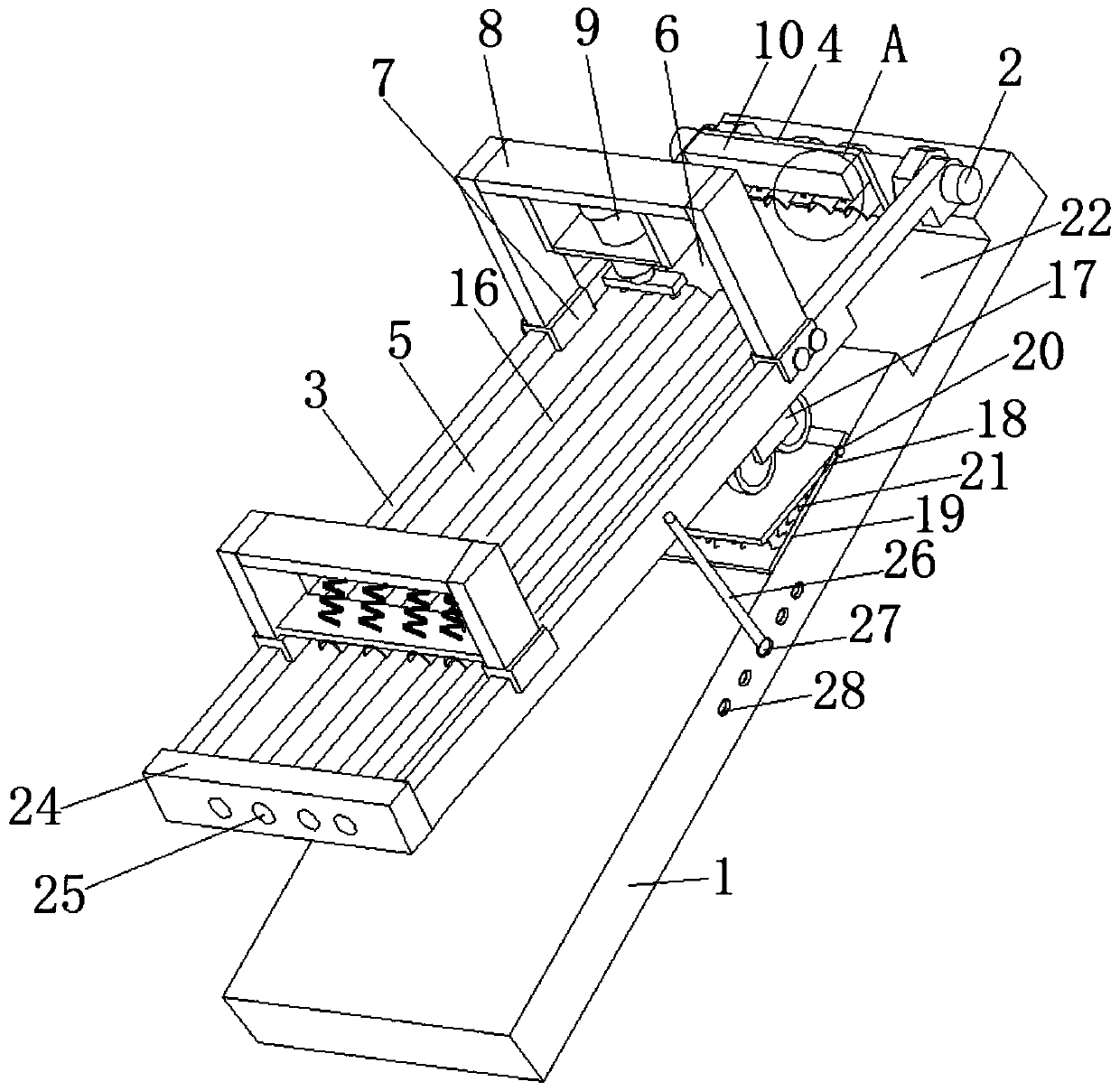
[0031] refer to figure 1 , a metal pipe cutting device, comprising a base 1, the top edge of the base 1 is movably connected with a rotating shaft 2 through a pole, both ends of the rotating shaft 2 are movably connected with baffles 3, and the middle section of the rotating shaft 2 is movably connected with The positioning plate 4 is connected with the feeding plate 5 between the baffle plate 3, the cutting table 6 is connected between the feeding plate 5 and the positioning plate 4, the baffle plate 3 is slidably connected with a slider 7, and the slider 7 is connected to the baffle by a bolt. The plate 3 is fixed, and the side of the slider 7 away from the baffle plate 3 is connected with a bracket 8, and the bracket 8 is connected with a cutting water jet assembly 9, and the cutting water jet assembly 9 is facing the cutting table 6, and by cutting directly facing the cutting table 6 The water jet assembly 9 realizes the cutting function of the metal pipe, drives the cutti...
Embodiment 2
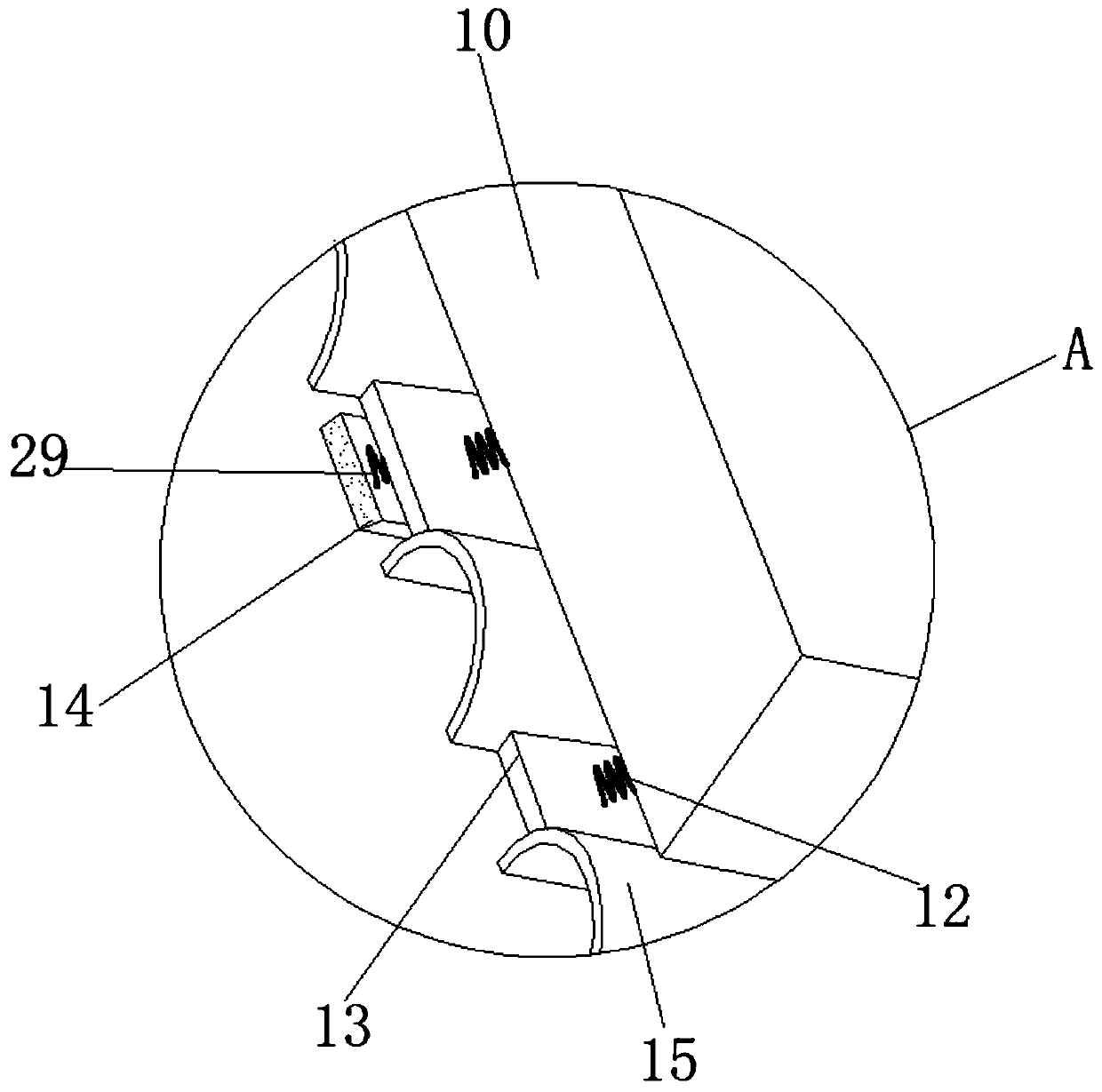
[0033] refer to Figure 1-6, a metal pipe cutting device, basically the same as Embodiment 1, the difference is that the positioning plate 4 and the cutting table 6 are perpendicular to each other, and the end of the positioning plate 4 away from the cutting table 6 is connected with a fixed block 10, and the fixed block 10 is close to One side of the cutting table 6 is provided with a groove, and a first electromagnet 11 is connected in the groove, and the end of the first electromagnet 11 away from the fixed block 10 is connected with a uniformly distributed first spring 12, and the first spring 12 is far away from the first spring 12. One end of electromagnet 11 is connected with iron block 13, and the bottom of iron block 13 is connected with second electromagnet 14, is connected with second spring 29 between iron block 13 and second electromagnet 14, connects between adjacent iron block 13. There is an arc-shaped limiting plate 15. When the metal pipe is cut, the first sp...
Embodiment 3
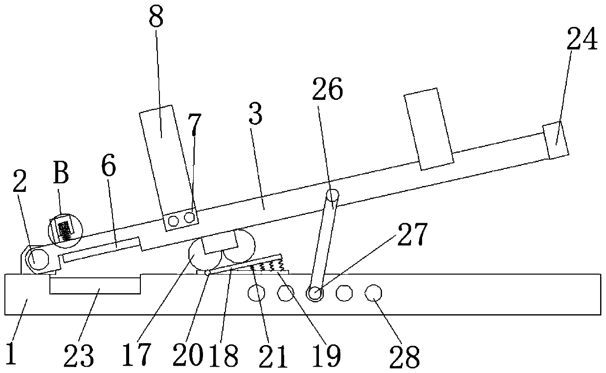
[0035] refer to Figure 1-6 , a metal pipe cutting device, basically the same as Embodiment 2, the difference is that the cutting table 6 includes a plate body 61, two cover plates 62 are movably connected to the bottom edge of the plate body 61, and the middle part of the plate body 61 is open. There is slotting, and the side of the slotting near the positioning plate 4 is connected with a fixed rod 63, and the outer wall of the fixed rod 63 is covered with a force spring 64, and one end of the force spring 64 is connected with an adjustment rod 65, and the adjustment rod 65 is connected with the draw-in groove. Flat, the other end of the power spring 64 is connected in the draw-in groove, and the adjusting rod 65 is connected with a traction rope 66 and a limit ring 67, and the traction rope 66 extends toward the positioning plate 4 through the limit ring 67, and the extension end is connected to the second The electromagnet 14 is fixedly connected, and the first electromagn...
PUM
 Abstract
Description
Claims
Application Information
 - R&D
- Intellectual Property
- Life Sciences
- Materials
- Tech Scout
- Unparalleled Data Quality
- Higher Quality Content
- 60% Fewer Hallucinations
Browse by: Latest US Patents, China's latest patents, Technical Efficacy Thesaurus, Application Domain, Technology Topic, Popular Technical Reports.
© 2025 PatSnap. All rights reserved.Legal|Privacy policy|Modern Slavery Act Transparency Statement|Sitemap|About US| Contact US: help@patsnap.com