Full-automatic quantitative filling machine for foaming cement

A foamed cement, fully automatic technology, applied in the direction of supply devices, manufacturing tools, etc., can solve the problems of complex control system, slow filling speed, easy to affect the accuracy of flowmeter, etc., and achieve the effect of accurate filling and reliable sealing

Pending Publication Date: 2019-01-01
GUANGXI SHENTA MACHINERY EQUIP CO LTD
View PDF10 Cites 0 Cited by
  • Summary
  • Abstract
  • Description
  • Claims
  • Application Information

AI Technical Summary

Problems solved by technology

[0002] Foamed cement has poor fluidity and poor working conditions, and it is difficult to accurately control the amount of grout in foamed cement blocks
There are two main types of existing multi-block automatic filling technologies for foamed cement: one is to install a flow meter at each filling port, send the block to the filling port, and inject the cement slurry into the inner cavity of the block through the flow meter. The advantage is that the cement filling amount of each filling port can be precisely controlled, but the flowmeter is limited by the volume. When there are many blocks and the inner cavity is small, the equipment is difficult to implement and the control system is relatively complicated. Moreover, the viscosity, corrosion and fluidity of the fluid The solids contained in the flowmeter are likely to affect the accuracy of the flowmeter; the other is the self-flow type, which is to send the block to the filling port, and the cement slurry flows into the cavity of the block through the filling port in a self-flowing manner. The advantage of controlling the filling amount is that the equipment structure is simple and the cost is low. The disadvantage is that the filling amount cannot be precisely controlled and the filling speed is slow.

Method used


Image

  • Full-automatic quantitative filling machine for foaming cement
  • Full-automatic quantitative filling machine for foaming cement
  • Full-automatic quantitative filling machine for foaming cement

Examples


Embodiment Construction

[0035] The present invention will be further described in detail below in conjunction with the accompanying drawings, so that those skilled in the art can implement it with reference to the description.

[0036] In the description of the present invention, the terms "transverse", "longitudinal", "upper", "lower", "vertical", "horizontal", "top", "bottom", "inner", "outer" etc. indicate The orientation or positional relationship is based on the orientation or positional relationship shown in the drawings, which is only for the convenience of describing the present invention and simplifying the description, and does not indicate or imply that the referred device or element must have a specific orientation or be configured in a specific orientation. and operation, and therefore should not be construed as limiting the invention.

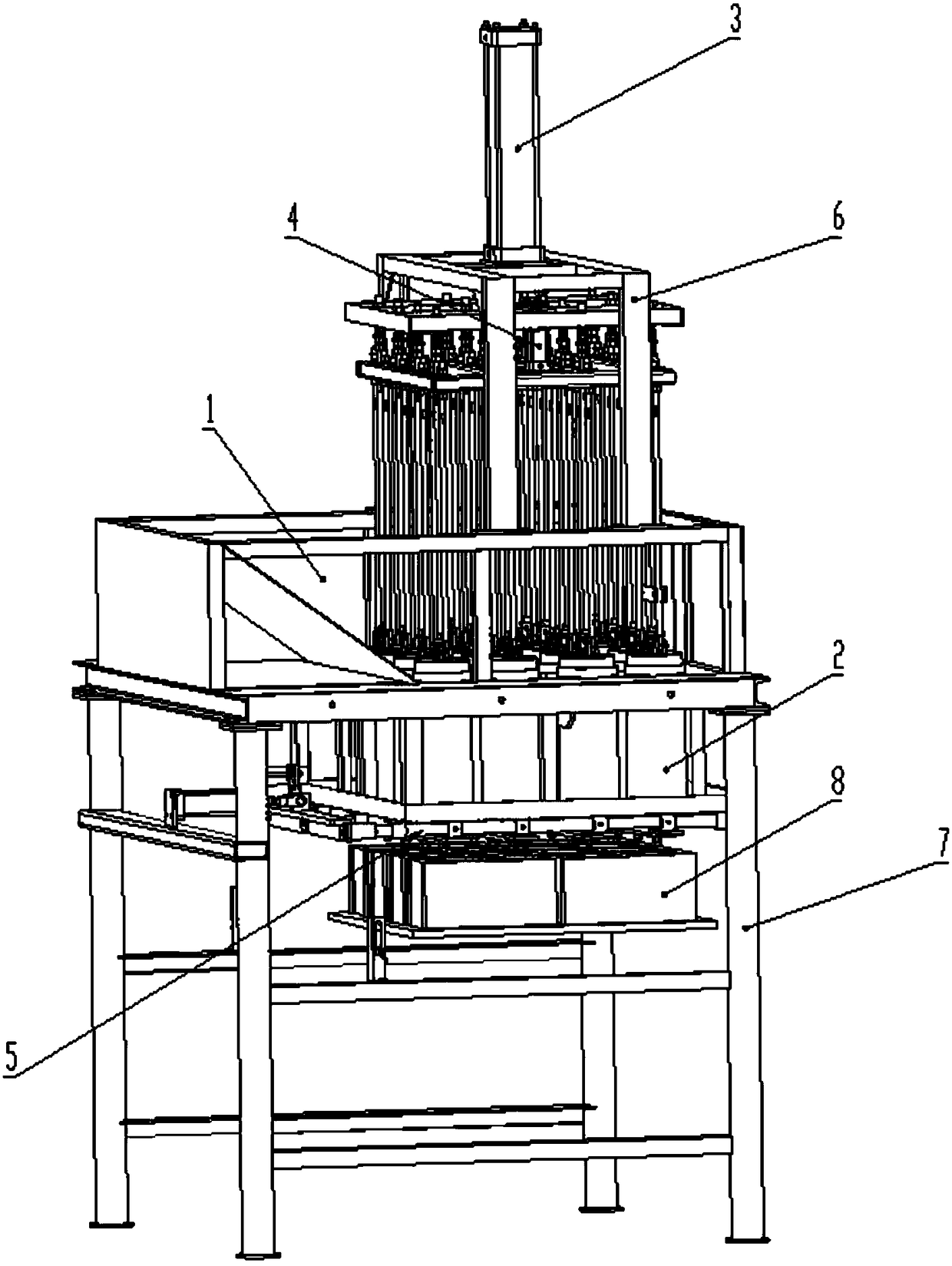
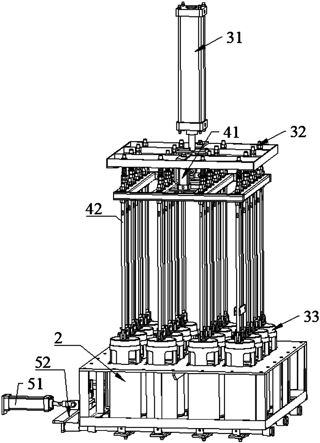
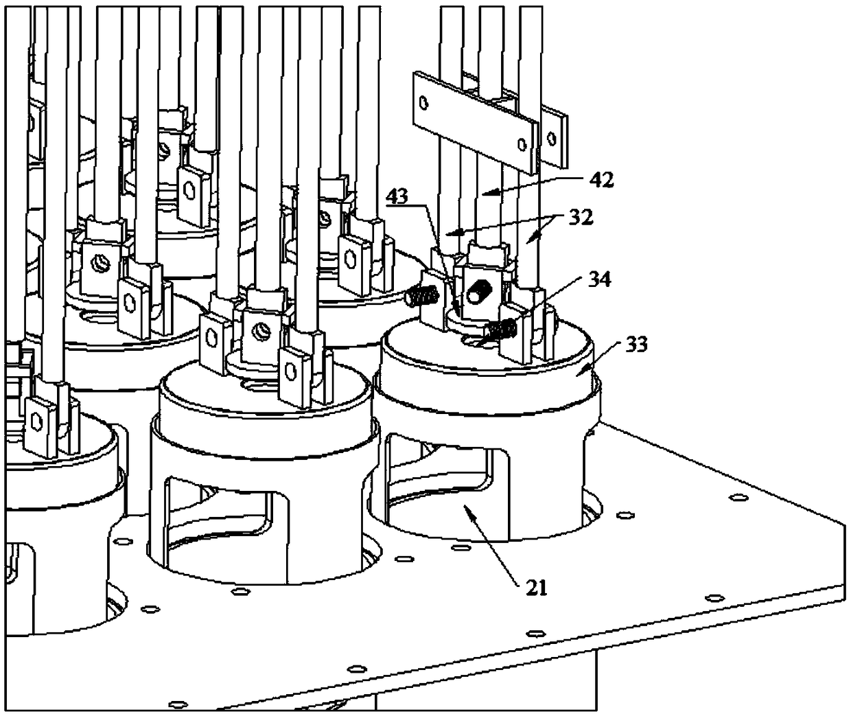
[0037] Such as Figure 1~5 As shown, the present invention provides a fully automatic quantitative filling machine for foamed cement, comprising:

[0...


PUM


Abstract

The invention discloses a full-automatic quantitative filling machine for foaming cement. The machine comprises a slurry storage pool, multiple injection pipes, a quantitative assembly, a plug assembly and a slurry door assembly. The top ends of the multiple injection pipes are sealed, penetrate through the bottom of the slurry storage pool and are located in the slurry storage pool. The quantitative assembly comprises a piston air cylinder located above the slurry storage pool, multiple first piston rods fixedly connected to the bottom end of an output shaft of the piston air cylinder and pistons connected to the bottom ends of the first piston rods correspondingly, the plug assembly comprises a plug air cylinder located above the slurry storage pool, multiple second piston rods fixedly connected to the bottom end of an output shaft of the plug air cylinder and piston plugs connected with the bottom ends of the second piston rods correspondingly, and the slurry door assembly comprisesa slurry door air cylinder, a connecting piece fixedly connected with an output shaft of the slurry door air cylinder and multiple slurry doors arranged on the connecting piece. The full-automatic quantitative filling machine has the beneficial effects that the filling amount is accurate, the structure is simple and easy to maintain, and multiple building block cavities with small sizes can be filled at the same time.

Description

technical field [0001] The invention relates to the field of automatic filling machines. More specifically, the present invention relates to a fully automatic quantitative filling machine for foamed cement. Background technique [0002] Foamed cement has poor fluidity and harsh working conditions, and it is difficult to accurately control the amount of grout in foamed cement blocks. There are two main types of existing multi-block automatic filling technologies for foamed cement: one is to install a flow meter at each filling port, send the block to the filling port, and inject the cement slurry into the inner cavity of the block through the flow meter. The advantage is that the cement filling amount of each filling port can be precisely controlled, but the flowmeter is limited by the volume. When there are many blocks and the inner cavity is small, the equipment is difficult to implement and the control system is relatively complicated. Moreover, the viscosity, corrosion a...

Claims


Application Information

Patent Timeline
Patent Type & Authority Applications(China)
IPC IPC(8): B28B13/02
CPCB28B13/0225
Inventor 覃金宇何长永
Owner GUANGXI SHENTA MACHINERY EQUIP CO LTD
Why Eureka
Try Eureka