Connection mechanism between joint and cross beam

A connecting mechanism and beam technology, applied in building components, building types, buildings, etc., can solve problems such as poor damping energy consumption, single damper form, and precise control of plastic hinge positions

Pending Publication Date: 2019-01-01
GUANGZHOU UNIVERSITY
View PDF4 Cites 1 Cited by
  • Summary
  • Abstract
  • Description
  • Claims
  • Application Information

AI Technical Summary

Problems solved by technology

But the disadvantage is that the current research has not been able to realize the precise control of the plas

Method used


Image

  • Connection mechanism between joint and cross beam
  • Connection mechanism between joint and cross beam
  • Connection mechanism between joint and cross beam

Examples


Embodiment Construction

[0030] The present invention will be further described in detail in conjunction with the accompanying drawings and specific embodiments.

[0031] In order to facilitate a unified review of the various reference signs in the drawings of the specification, the unified description of the reference signs appearing in the drawings of the specification is as follows:

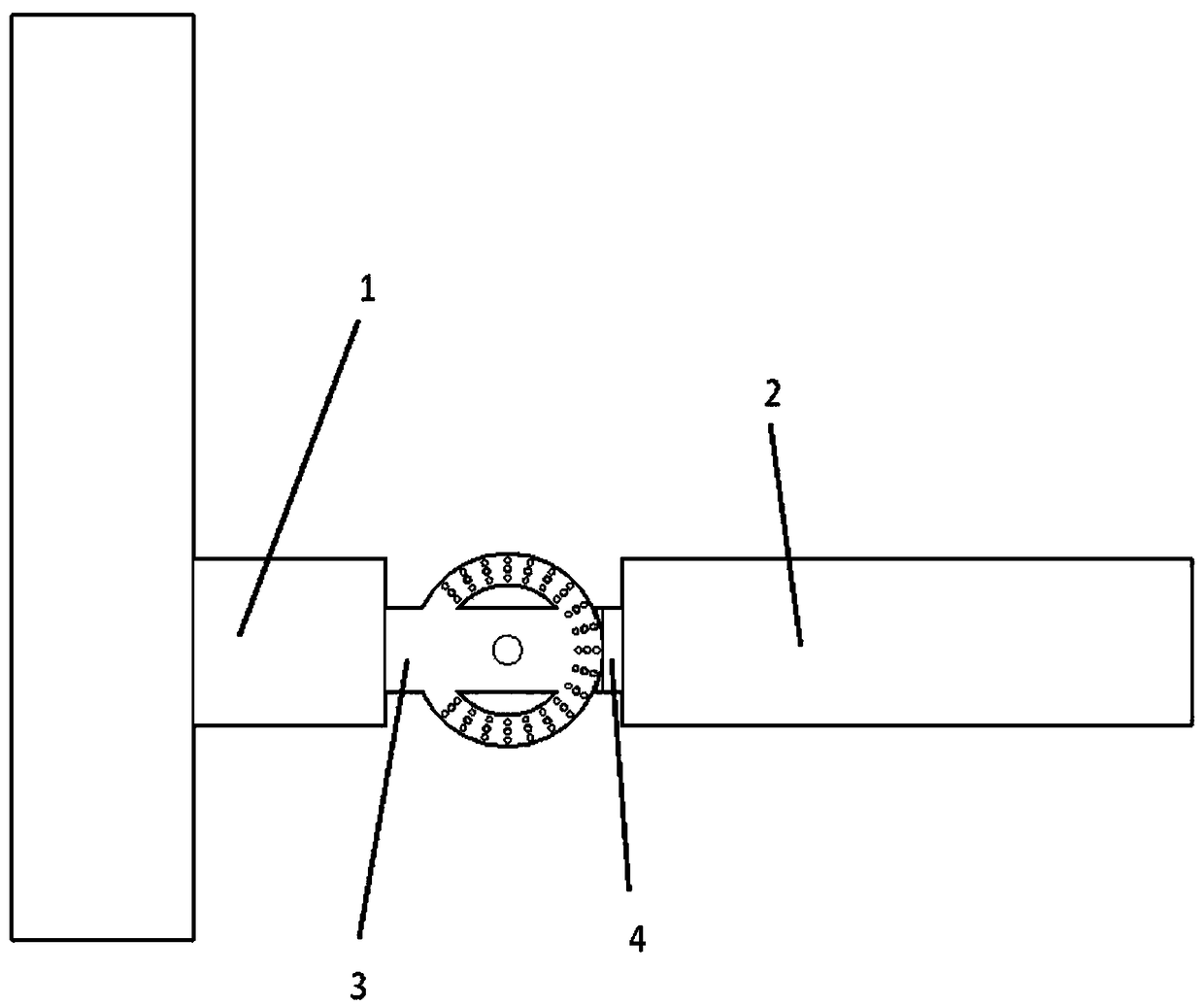
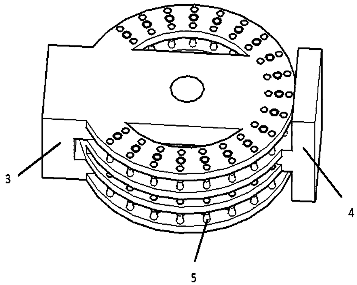
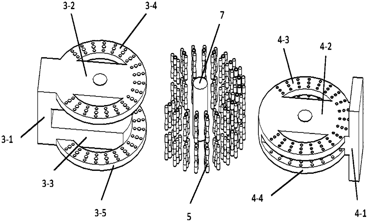
[0032] 1 is the node, 2 is the beam, 3 is the first connection part, 4 is the second connection part, 5 is the second type of damping part, 6 is the first type of damping part, 7 is the rotating shaft, 3-1 is the first fixed block , 3-2 is the front plate, 3-3 is the rear plate, 3-4 is the first ring plate, 3-5 is the second ring plate, 4-1 is the second fixed block, 4-2 is the middle plate , 4-3 is the third circular plate, 4-4 is the fourth circular plate, 5-1 is the first cylindrical part, 5-2 is the first circular truncated part, 5-3 is the second circular truncated part, 5- 4 is the second cylindrical part, and ...


PUM


Abstract

The invention relates to a connection mechanism between a joint and a cross beam. The connection mechanism between the joint and the cross beam comprises a first connection part and a second connection part, wherein the first connection part and the second connection part are rotatably installed together. The first connection part comprises a front plate, a rear plate, a first fixed block, a firstannular plate integrally formed with the front plate and a second annular plate integrally formed with the rear plate, wherein the front plate is connected with the rear plate through the first fixedblock. The second connecting part comprises a second fixed block, a middle plate fixed to the second fixed block, a third annular plate and a fourth annular plate, wherein the third annular plate andthe fourth annular plate are integrally formed with the middle plate. The third annular plate is located in front of the fourth annular plate, the rear end face of the front plate is in contact withthe front end face of the third annular plate, the rear end face of the fourth annular plate is in contact with the front end face of the rear plate, the front plate, the rear plate and the middle plate are connected together through a rotating shaft, the first fixed block is fixed to the joint, and the second fixed block is fixed to the cross beam. The connecting mechanism has good damping and energy dissipation effects, and belongs to the technical field of earthquake resistance of houses.

Description

technical field [0001] The invention relates to the technical field of anti-seismic buildings, in particular to a connection mechanism between nodes and beams. Background technique [0002] Earthquake disasters have been one of the most serious natural disasters faced by human beings since ancient times. They are extremely random, unpredictable and widely spread, and seriously threaten human survival and social development. Frequent strong earthquakes in recent years have caused massive damage to building structures, resulting in a large number of casualties and property losses. [0003] Based on the research status of energy dissipation and shock absorption of prefabricated structures at home and abroad, it can be seen that due to its own limitations, the energy dissipation capacity of prefabricated structures under earthquakes has certain limitations. Therefore, in order to improve the seismic performance of prefabricated structures , the introduction of energy-dissipatin...

Claims


Application Information

Patent Timeline
IPC IPC(8): E04B1/98E04H9/02
CPCE04H9/021
Inventor 叶茂傅继阳
Owner GUANGZHOU UNIVERSITY
Why Eureka
Try Eureka