Fan frame structure

A fan frame and wire structure technology, applied in the direction of instruments, electrical digital data processing, digital data processing parts, etc., can solve the problems of reducing the service life of the fan, reducing the structural strength of the supporting parts, and affecting the quality of the fan frame, and reducing the operation. Noise, airflow concentration, and the effect of improving fan performance

Inactive Publication Date: 2019-01-01
DELTA ELECTRONICS INC
View PDF9 Cites 0 Cited by
  • Summary
  • Abstract
  • Description
  • Claims
  • Application Information

AI Technical Summary

Problems solved by technology

However, the noise reduction method of the above-mentioned destructive structure will cause the strength of the support structure to be greatly reduced, which will affect the quality of the fan frame and reduce the service life of the fan

Method used


Image

  • Fan frame structure
  • Fan frame structure
  • Fan frame structure

Examples


Embodiment Construction

[0043] The fan frame structure according to the preferred embodiment of the present invention will be described below with reference to the related drawings, wherein the same elements will be described with the same reference symbols.

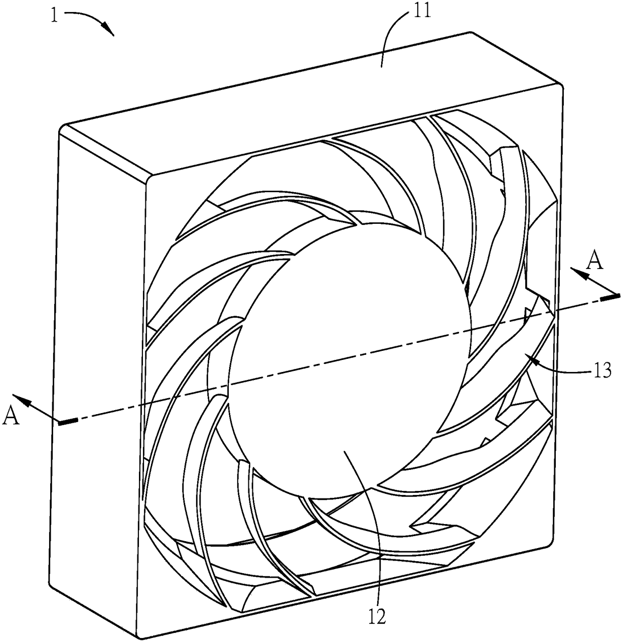
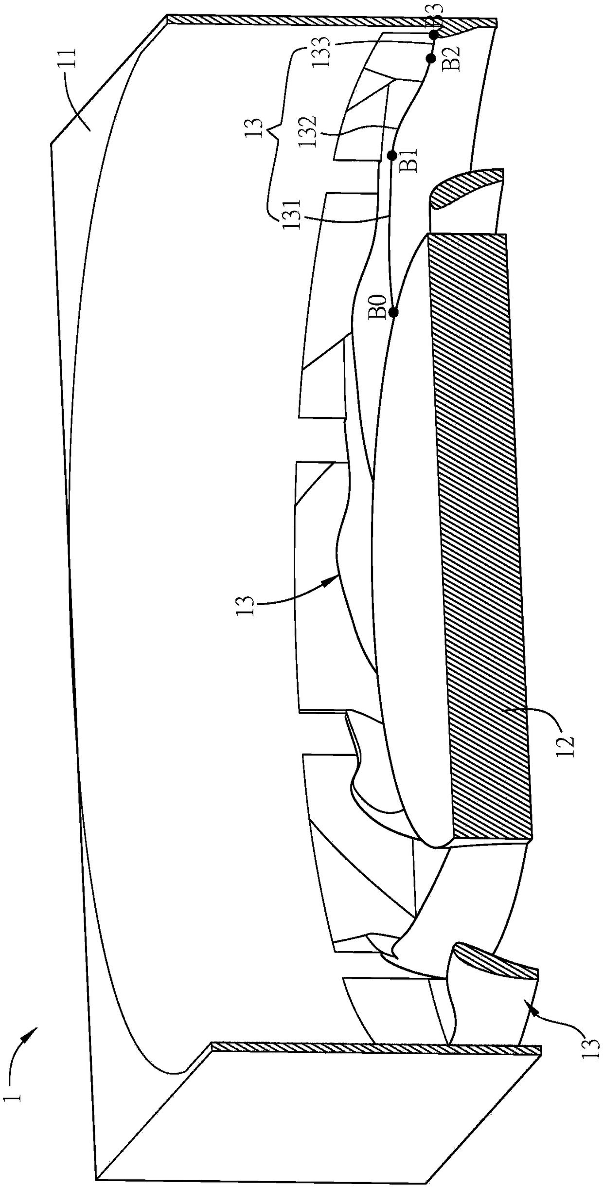
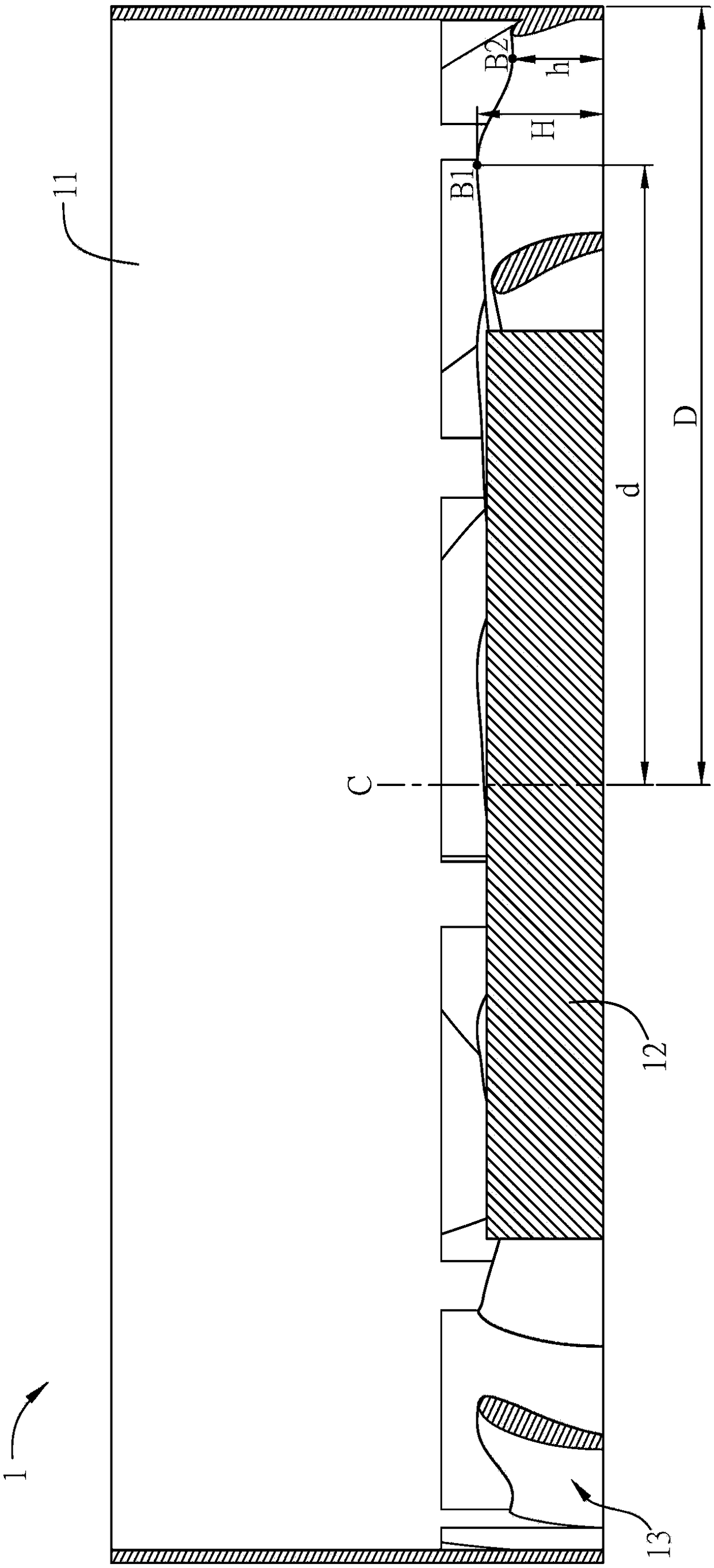
[0044] Please also refer to figure 1 , Figure 2A as well as Figure 2B , figure 1 It is a three-dimensional schematic diagram of a fan frame structure in a preferred embodiment of the present invention, Figure 2A for figure 1 The three-dimensional cross-sectional view of the fan frame structure shown along the line segment A-A, Figure 2B for Figure 2A The plane section view of the fan frame structure shown.

[0045] The present invention provides a fan frame structure 1 including a frame body 11 , a base 12 and a plurality of supporting parts 13 . The base 12 is disposed in the frame body 11 . A plurality of support members 13 are disposed around the periphery of the base 12 and connected between the base 12 and the frame body 11 . ...


PUM


Abstract

The invention discloses a fan frame structure. The fan frame structure comprises a frame body, a base and a plurality of supporting pieces. The base is arranged in the frame body, and the plurality ofsupporting pieces are annularly arranged on the periphery of the base and are connected between the base and the frame body. Each supporting piece has a body portion and a sudden dropping portion, and the sudden dropping portions face a windward side of the frame body and are located between the body portions and the frame body. The ratio of the minimum height of the sudden dropping portions andthe maximum height of the body portions is 0.82-0.92.

Description

technical field [0001] The invention relates to a fan frame structure, in particular to a fan frame structure with a support member having a sudden drop position. Background technique [0002] The cooling modules used in general electronic devices usually use fans to take away the heat directly or indirectly, so the performance of the fans will directly affect the cooling performance of the electronic devices. When the fan is running, the airflow generated by the high-speed rotation of the fan blades will collide with the fan frame and generate running noise, which is one of the main noise sources of the fan. And because the internal flow field of the fan is very complicated, especially in the gap between the end of the fan blade and the outer frame of the frame, the air flow will produce overflow and backflow phenomena, and the flow field entering the fan frame is affected by the disturbance of the air flow, making the air flow not concentrated This in turn results in redu...

Claims


Application Information

Patent Timeline
Patent Type & Authority Applications(China)
IPC IPC(8): F04D29/42F04D25/08G06F1/20
CPCF04D25/08F04D29/4206G06F1/20F04D19/002F04D29/544F04D29/663F04D29/667
Inventor 杨朝富
Owner DELTA ELECTRONICS INC
Why Eureka
Try Eureka