Air source heat pump air heater system and control method thereof

An air source heat pump and hot air blower technology, which is applied to air heaters, heat pumps, refrigerators, etc., can solve problems such as the system cannot run stably and normally

Inactive Publication Date: 2019-01-01
GUANGDONG CHIGO HEATING & VENTILATION EQUIP CO LTD
View PDF5 Cites 1 Cited by
  • Summary
  • Abstract
  • Description
  • Claims
  • Application Information

AI Technical Summary

Problems solved by technology

[0004] The embodiment of the present application provides an air source heat pump fan system and control method, which solves the technical problem that the system

Method used


Image

  • Air source heat pump air heater system and control method thereof
  • Air source heat pump air heater system and control method thereof
  • Air source heat pump air heater system and control method thereof

Examples


Embodiment Construction

[0045] In order to enable those skilled in the art to better understand the solution of the present application, the technical solution in the embodiment of the application will be clearly and completely described below in conjunction with the accompanying drawings in the embodiment of the application. Obviously, the described embodiment is only It is a part of the embodiments of this application, not all of them. Based on the embodiments in this application, all other embodiments obtained by persons of ordinary skill in the art without making creative efforts belong to the scope of protection of this application.

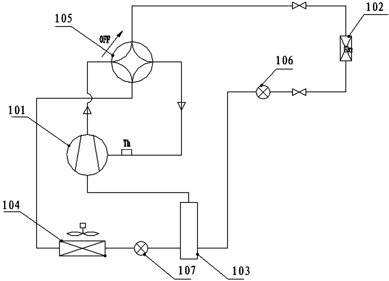
[0046] For ease of understanding, see figure 1 , figure 1 It is a schematic structural diagram of an embodiment of an air source heat pump fan system provided in this application.

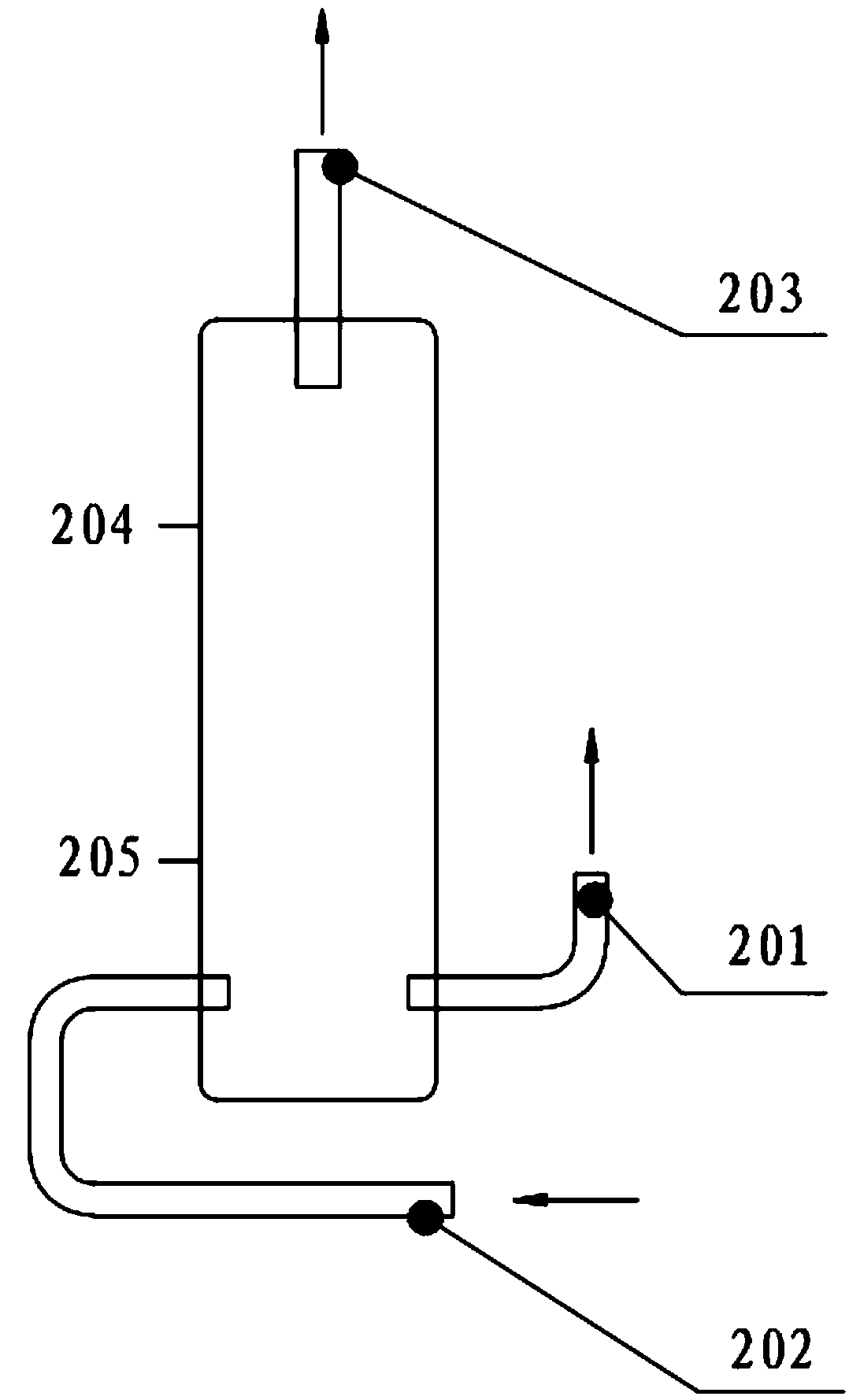
[0047] The system includes a compressor 101, an internal heat exchanger 102, a flash evaporator 103, an external heat exchanger 104 and a control device.

[0048]Wherein, the compres...


PUM


Abstract

The embodiment of the invention discloses an air source heat pump air heater system. Control valves are arranged at the positions of two liquid ports of a flash evaporator, and the flash evaporator isprovided with a liquid level monitoring device. The embodiment of the invention further discloses a method for controlling the above system. The method comprises the steps that whether the liquid level of the flash evaporator is in the preset range or not is judged, if the liquid level of the flash evaporator is not in the preset range, the liquid level tends to be in the preset range through adjustment of the opening degree of the control valve at the liquid inlet of the flash evaporator, and whether the liquid level of the flash evaporator is in the preset range or not is judged again; andwhether the air return overheat degree of the system is in the preset overheat degree range or not is judged, if the air return overheat degree of the system is not in the preset overheat degree range, the air return overheat degree tends to be in the preset overheat degree range through adjustment of the opening degree of the control valve at the liquid outlet of the flash evaporator, and whetherthe air return overheat degree of the system is in the preset overheat degree range or not is judged again. The technical problem that since the liquid level of the flash evaporator and the circularflow of a main loop refrigerant are not in the reasonable range, a system cannot stably and normally run is solved.

Description

technical field [0001] The present application relates to the technical field of air conditioning, in particular to an air source heat pump fan system and a control method thereof. Background technique [0002] With the implementation of the coal-to-electricity policy in the north, coal-fired air-conditioning equipment is gradually being eliminated, and the air source heat pump fan is widely favored by the market due to its low investment cost and flexible installation. [0003] At present, there are some air source heat pump fan products on the market. The system uses a flash evaporator to improve the performance of the compressor, but the liquid level of the flash evaporator is not well controlled. If the liquid level of the flash evaporator is too high, the liquid refrigerant may enter the compressor. machine, causing system abnormality, the liquid level of the flash evaporator is too low, the main circuit refrigerant circulation flow is unstable, the system will also be ...

Claims


Application Information

Patent Timeline
IPC IPC(8): F24H3/08F24H9/20F25B30/06
CPCF24H3/08F24H9/2064F25B30/06
Inventor 陈卫东陆勇祥周万兵朱健文
Owner GUANGDONG CHIGO HEATING & VENTILATION EQUIP CO LTD
Why Eureka
Try Eureka