Electromagnetic-type power-off brake suction force testing device

A technology of power-off brakes and testing devices, which is applied in measuring devices, force/torque/power measuring instruments, instruments, etc., and can solve the problems that the brakes cannot exert their maximum performance and cannot meet the requirements of accurate measurement of brake suction force, etc.

Active Publication Date: 2019-01-01
HARBIN INST OF TECH
View PDF5 Cites 4 Cited by
  • Summary
  • Abstract
  • Description
  • Claims
  • Application Information

AI Technical Summary

Problems solved by technology

[0004] The technical problem to be solved in the present invention is: the existing test device for the pull-in force cannot accurately measure the pull-in force of the brak

Method used


Image

  • Electromagnetic-type power-off brake suction force testing device
  • Electromagnetic-type power-off brake suction force testing device
  • Electromagnetic-type power-off brake suction force testing device

Examples


specific Embodiment approach 1

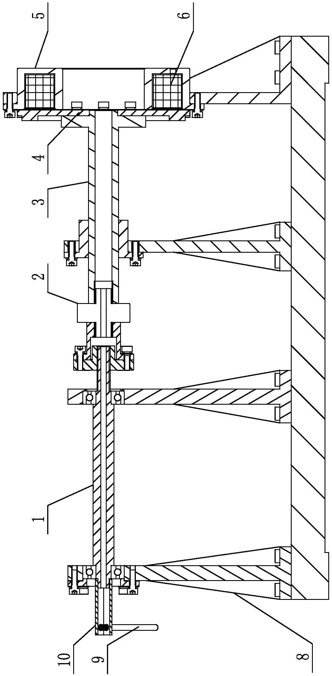
[0016] Specific implementation mode one: combine figure 1 and figure 2 To illustrate this embodiment, the device for testing the pull-in force of an electromagnetic power-off brake described in this embodiment includes an axial displacement precision adjustment device 1, a load cell 2, an armature friction disc support device 3, an armature friction disc 4, and a brake housing 5 , electromagnetic coil 6 and support frame 8; described axial displacement precise adjustment device 1, armature friction disc support device 3 and brake housing 5 are respectively horizontally installed on the support frame 8 in turn; described support frame 8 is installed by screws on a fixed base;

[0017] One end of the load cell 2 is connected to the precise adjustment device 1 for axial displacement, the other end is connected to one end of the armature friction disc support device 3, and the other end of the armature friction disc support device 3 is connected to the armature friction disc 4 ...

specific Embodiment approach 2

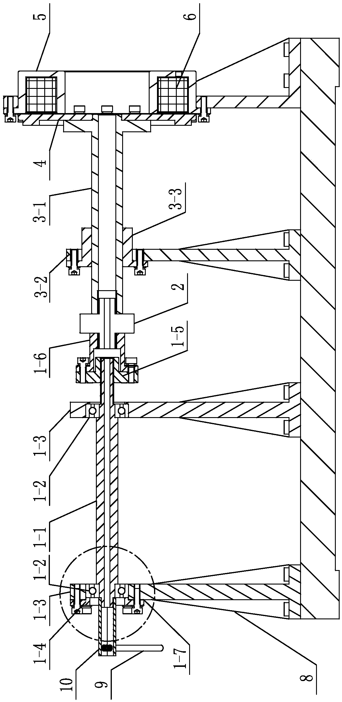
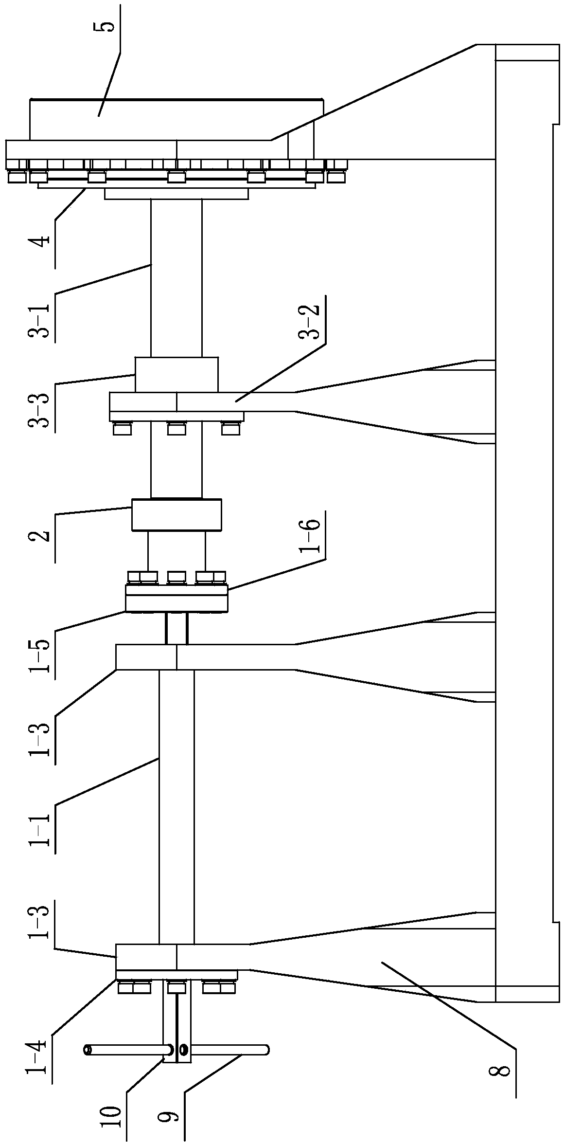
[0021] Specific implementation mode two: combination Figure 2-5 Describe this embodiment, the axial displacement precise adjustment device 1 described in this embodiment includes a screw shaft 1-1, two angular contact ball bearings 1-2, a screw nut 1-5 and two bearing support seats 1- 3. The two bearing support bases 1-3 are located above the support frame 8 and integrally formed with the support frame 8; the two ends of the screw shaft 1-1 are respectively fixed and installed in the two bearing support bases 1-3 In the inner rings of the two angular contact ball bearings 1-2, and extend two bearing support seats 1-3; the end of the screw shaft 1-1 protruding from the bearing support seat is connected with a displacement loading device, and in addition The outer wall at one end has an external thread and is covered with a screw nut 1-5; the screw nut 1-5 is fixedly connected to one end of the load cell 2; the screw shaft is under the action of the displacement loading device ...

specific Embodiment approach 3

[0023] Specific implementation mode three: combination Figure 2-6 To illustrate this embodiment, the screw shaft 1-1 described in this embodiment is a trapezoidal screw, and the inner side walls of the inner rings of the two angular contact ball bearings 1-2 respectively abut against the shoulders at both ends of the screw shaft 1-1 , the outer walls of the outer rings of the two angular contact ball bearings 1-2 are respectively blocked by the card seat in one of the bearing support seats 1-3 and the bearing cover 1-4 screwed to the outer wall of the other bearing support seat 1-3 . Under the action of two angular contact ball bearings, bearing cover and bearing support seat, the screw shaft does not produce displacement in the axial direction. Therefore, the distance that the load cell moves in the axial direction is continuously and gradually increased without repeating movement in the axial direction.

[0024] like Figure 7 As shown: an adjusting gasket 1-7 is also in...


PUM


Abstract

The invention discloses an electromagnetic-type power-off brake suction force testing device, and relates to a brake testing device. The invention aims at solving a problem that a conventional suctionforce testing device cannot meet the requirements of precise measurement of the electromagnetic suction force of a brake. The device comprises an axial displacement precision adjustment device, a load cell, an armature friction disc support device, an armature friction disc, a brake housing, an electromagnetic coil and a support frame. One end of the load cell is connected to the axial displacement precision adjustment device, the other end is connected with one end of the armature friction disc support device, and the other end of the armature friction disc support device is fixedly connected with one side of the armature friction disc. The load cell moves in the stroke direction of the load cell under the drive of the axial displacement precise adjustment device. The electromagnetic coil is installed in an annular groove in the brake housing, and the brake housing and the armature friction disc are magnetically connected by an electromagnetic force generated by the electromagnetic coil. The device is used for accurately measuring the suction force of the electromagnetic coil to the armature friction disc.

Description

technical field [0001] The invention belongs to the field of brakes, and relates to a test device for a brake, in particular to a test device for the attraction force of an electromagnetic power-off brake. Background technique [0002] Brakes are mainly used to decelerate or stop moving parts, usually called brakes or brakes, and are widely used in aerospace, robotics, automation and other fields. Electromagnetic power-off brake is a kind of brake that separates when it is powered on and brakes when it is powered off. The brake uses the electromagnetic coil to generate a magnetic field under the condition of electrification, thereby attracting the armature friction disc and separating the armature friction disc from the rotating friction disc; The friction discs contact to generate friction torque to form a brake. [0003] Patent CN 107478372 A discloses a permanent magnet brake electromagnetic attraction test device, which uses a mass block to test the electromagnetic att...

Claims


Application Information

Patent Timeline
IPC IPC(8): G01L5/28
CPCG01L5/28
Inventor 孙永军张元飞郭闯强刘伊威金明河刘宏
Owner HARBIN INST OF TECH
Why Eureka
Try Eureka