
Optical network measuring device and measuring method for flying target

A technology for flying targets and measuring devices, which is applied to the field of optical network measuring devices for flying targets, can solve problems such as the destruction, destruction, and grid measurement function failure of flying targets, and achieves the effect of good repeatability and meeting the requirements of measurement accuracy.

Inactive Publication Date: 2019-01-01
中国空气动力研究与发展中心超高速空气动力研究所
View PDF6 Cites 0 Cited by
  • Summary
  • Abstract
  • Description
  • Claims
  • Application Information

AI Technical Summary

Problems solved by technology

[0003] At present, in order to meet the target position and size measurement requirements of space-based platforms and other places, a method for measuring the position and size of target impact points based on fiber grids is proposed, and there is also a low-power impact point based on wire grids. Information measurement device, the common point of these two methods is that every measurement of the target will destroy a part of the grid, which not only leads to the complete failure of the measurement function of the grid, but also causes certain damage to the flying target

Method used


Image

  • Optical network measuring device and measuring method for flying target
  • Optical network measuring device and measuring method for flying target
  • Optical network measuring device and measuring method for flying target

Examples


specific Embodiment approach 1

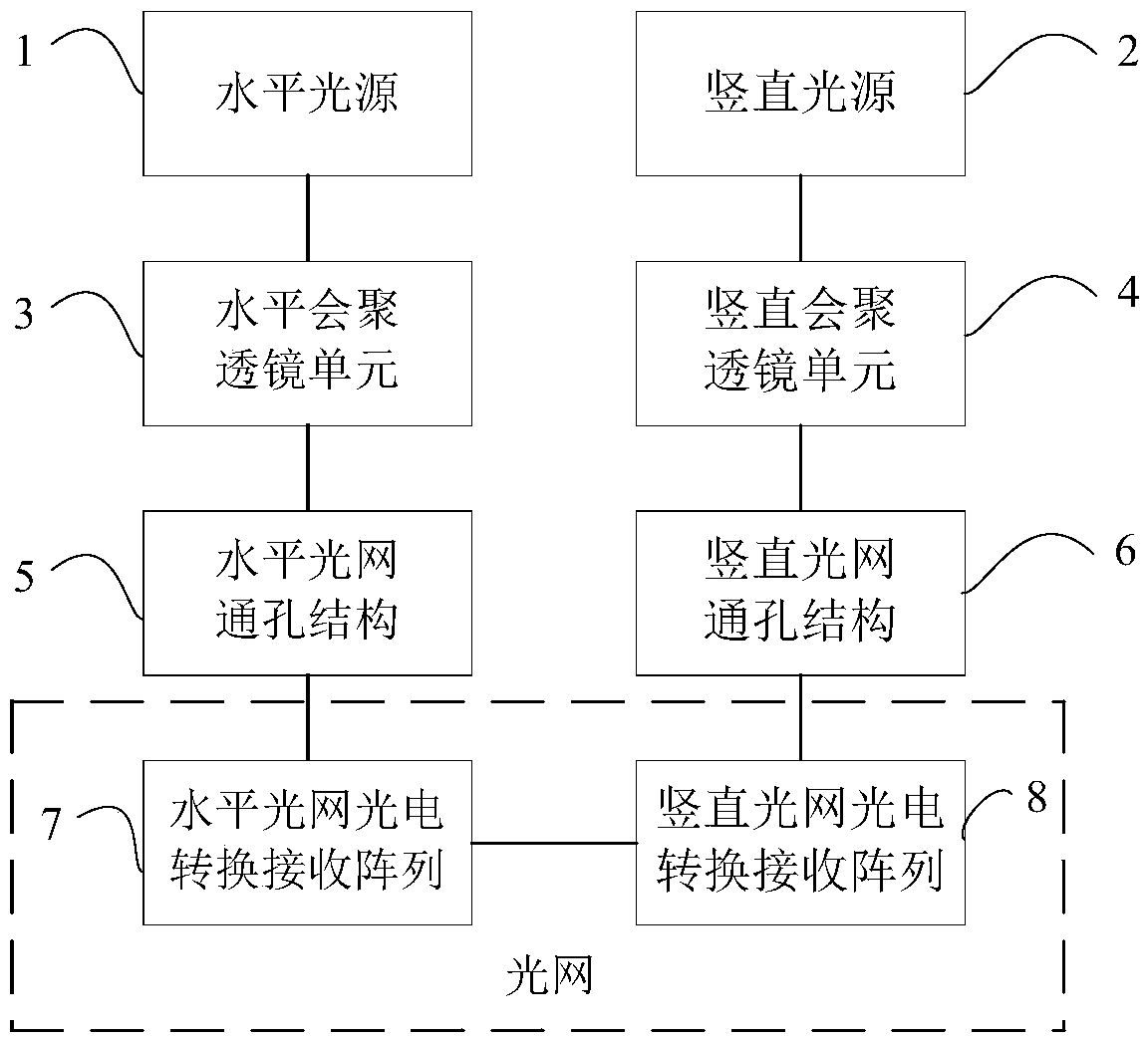
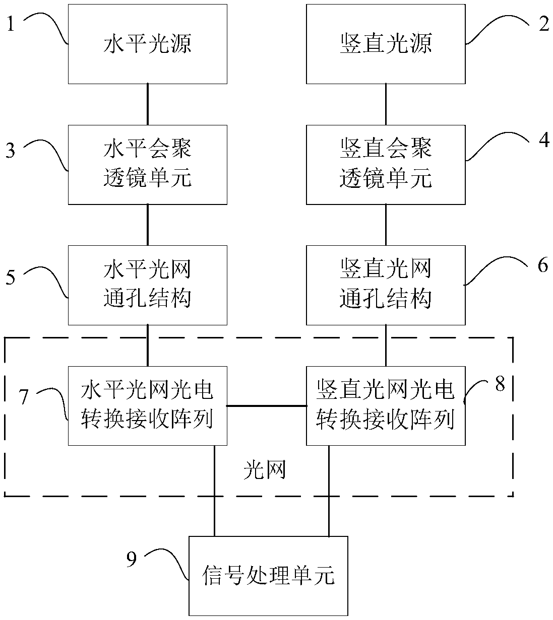
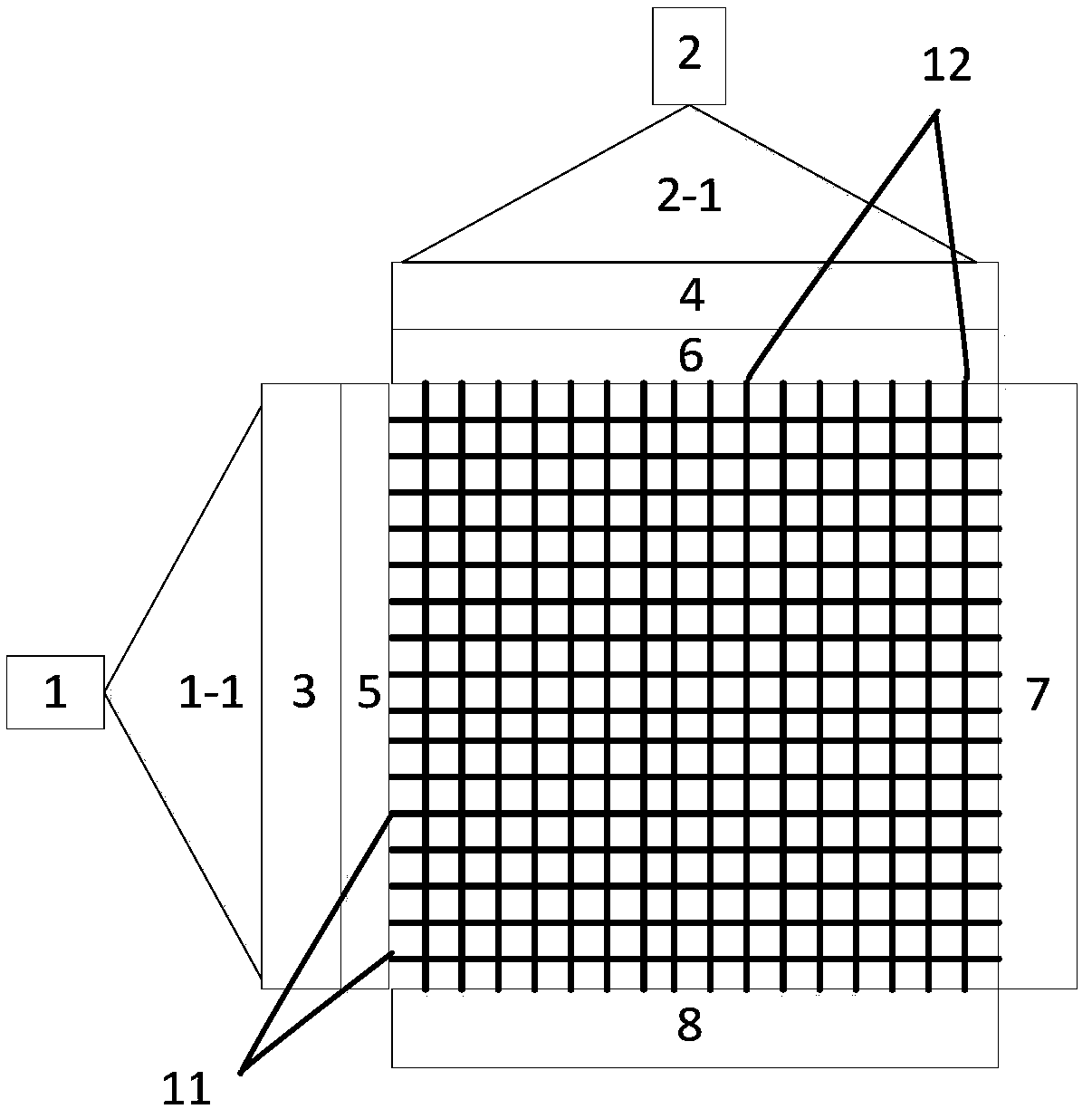
[0031] DETAILED DESCRIPTION OF THE PREFERRED EMBODIMENT 1. The first aspect of the present invention provides an optical network measurement device for a flying target, including an optical network array generation module for forming orthogonal grid light, and an optical network array generating module for receiving orthogonal grid light respectively. The photoelectric conversion receiving array of the optical signal of the horizontal optical network and the vertical optical network.

[0032] The invention is designed to solve the problem that the measurement equipment interacts with the flying target and causes mutual damage in the existing method for measuring the flying target. It is designed based on the fact that the signal will change after the light is blocked by the object but does not cause substantial damage, and then the optical signal received by the photoelectric conversion receiving array determines the change of the state of the optical network, which can be used...

specific Embodiment approach 2

[0052] Specific Embodiment 2. Another aspect of the present invention also provides a method for measuring the optical network of a flying target, which is implemented based on the device for measuring the optical network of the flying target. The method for measuring the optical network includes:

[0053] According to the shielding of the light signal when the flying target passes through the orthogonal grid light, the orientation and size of the flying target are recognized.

[0054] In specific use, each grid of the horizontal optical network and the vertical optical network can be numbered separately. For example, for the orthogonal grid light, the optical grid can be layered into 1, 2, 3... ... layer, for the grids of each layer, mark the row and column numbers of the unit grids respectively, so that the specific position of each grid in the orthogonal grid light can be determined according to the number, so as to carry out the flight target position and Calculation of di...


PUM


Abstract

The invention relates to an optical network measuring device and measuring method for a flying target. The measuring device comprises an optical network array generating module for forming orthogonalgrid light and a photoelectric conversion receiving array for receiving optical signals of a horizontal optical network and a vertical optical network in the orthogonal grid light respectively. In addition, the measuring method includes: an orientation and a size of a flying target are identified according shielding of an optical signal during orthogonal grid light passing by the flying target. During the measuring process, the flying target only shields the light instead of damaging the light and the flying target is not affected by the optical network, so that the repeatability of usage of the measuring device on occasions like a space-based platform is improved.

Description

technical field [0001] The invention relates to the technical field of measuring flying targets, in particular to an optical network measuring device and a measuring method for flying targets. Background technique [0002] At present, common methods for measuring the position and size of flying targets include optical imaging and radar detection. Not satisfactory. For example, for ultra-high-speed flying targets, if optical imaging is used to measure their position and size, a high-speed camera with ultra-high frame rate is required, otherwise the imaging will produce motion blur; especially for small targets of centimeter and millimeter levels, high-speed The camera has high image resolution. In this case, the optical imaging measurement method will generate a large amount of measurement data, which requires complex processing in the later stage. If the radar detection method is used to measure the same ultra-high-speed and small-sized flying target, there are also probl...

Claims


Application Information

Patent Timeline
Patent Type & Authority Applications(China)
IPC IPC(8): G01V8/20G01B11/00
CPCG01B11/002G01V8/20
Inventor 文雪忠黄洁柳森姜林李晶宋强罗锦阳罗庆赵浩龙
Owner 中国空气动力研究与发展中心超高速空气动力研究所
Learn More