
Driving circuit and a light emitting display device

A driving circuit and driving power technology, applied in the field of power electronics, can solve the problems of complex MOSFET tube connection circuit, complex high-voltage DC circuit and high cost

Inactive Publication Date: 2019-01-01
SHANGHAI MI FANG ELECTRONICS LTD
View PDF6 Cites 0 Cited by
  • Summary
  • Abstract
  • Description
  • Claims
  • Application Information

AI Technical Summary

Problems solved by technology

The above-mentioned prior art uses high-voltage direct current to control the MOSFET tube to be turned on or off. The corresponding high-voltage direct current circuit is relatively complicated, and the connection circuit of the MOSFET tube is complicated, and the cost of emitting light through common high-voltage switching chip control is relatively high.
In addition, the current voltage signal controlled by DC voltage is a square wave signal, which has large interference and cannot accurately control the corresponding inorganic electroluminescent device to emit light.

Method used


Image

  • Driving circuit and a light emitting display device
  • Driving circuit and a light emitting display device
  • Driving circuit and a light emitting display device

Examples


Embodiment Construction

[0024] The present application is described below based on examples, but the present application is not limited only to these examples. In the following detailed description of the application, some specific details are set forth in detail. The present application can be fully understood by those skilled in the art without the description of these detailed parts. To avoid obscuring the essence of the present application, well-known methods, procedures, procedures, components and circuits have not been described in detail.

[0025] Additionally, those of ordinary skill in the art will appreciate that the drawings provided herein are for illustrative purposes and are not necessarily drawn to scale.

[0026] Meanwhile, it should be understood that in the following description, "circuit" refers to a conductive loop formed by at least one element or sub-circuit through electrical connection or electromagnetic connection. When an element or circuit is said to be "connected to" ano...


PUM


Abstract

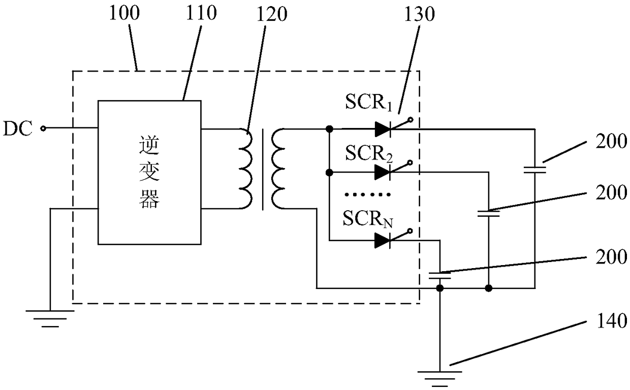
A driving circuit and a light emitting display device are disclosed. The driving circuit includes an inverter, a transformer and at least one trigger circuit. The inverter is connected with a DC inputport. The transformer is connected with the output ports of the inverters. Each trigger circuit is arranged between the transformer and the electrodes of an electroluminescent unit. The driving circuit converts DC power into AC power, boosts the AC power and applies the AC power to the trigger circuits. When each trigger circuit is triggered, the corresponding electroluminescent unit is driven through one-way conduction to emit light. The driving circuit of the application is simple, costs low, and can accurately make the electroluminescent units emit light.

Description

technical field [0001] The present application relates to the technical field of power electronics, in particular to a driving circuit and a light-emitting display device. Background technique [0002] Most of the existing circuits for driving electroluminescent devices to perform light-emitting display adopt DC voltage. -Oxide Semiconductor Field Effect Transistor, MOSFET) or a high-voltage breaking chip controls the breaking of high-voltage DC. When the driving circuit generates the working conditions required by the MOSFET, the MOSFET is turned on, and the electroluminescent device or electroluminescent device connected to the MOSFET is turned on. The specified light-emitting segment in the light-emitting device performs light-emitting display. The above-mentioned prior art uses high-voltage direct current to control the MOSFET to turn on or off. The corresponding high-voltage direct current circuit is relatively complicated, and the connection circuit of the MOSFET is c...

Claims


Application Information

Patent Timeline
IPC IPC(8): G09G3/30H05B33/08H05B44/00
CPCG09G3/30H05B44/00
Inventor 程辉任大勇魏勤李胜夏
Owner SHANGHAI MI FANG ELECTRONICS LTD
Learn More