Circular connector and connector assembly

A technology of circular connectors and connector assemblies, which is applied in the parts, connections, electrical components of the connecting device, etc., can solve the problems of damage to the sealing ring, scratch the sealing ring, large resistance, etc. Effort-saving and low-resistance effect

Active Publication Date: 2019-01-01
CHINA AVIATION OPTICAL-ELECTRICAL TECH CO LTD
View PDF4 Cites 3 Cited by
  • Summary
  • Abstract
  • Description
  • Claims
  • Application Information

AI Technical Summary

Problems solved by technology

[0003] However, the above-mentioned connector has the following problems: the space between the connecting sleeve and the spline housing is narrow, and after a sealing ring is arranged in this space, when the connecting sleeve is a screw sleeve, when the screw sleeve is screwed, the inner thread of the screw sleeve It will scratch the sealing ring; when the connecting sleeve is a buckle connecting sleeve, although there is no thread inside the connecting sleeve, when the connecting sleeve is screwed, the sealing ring will still be damaged due to the friction between the inner peripheral surface of the connecting sleeve and the sealing ring. crush damage
Therefore, these two kinds of connecting sleeves will damage the sealing ring, which will affect the service life of the sealing ring. At the same time, the resistance during the screwing process is relatively large, which is very laborious.

Method used


Image

  • Circular connector and connector assembly
  • Circular connector and connector assembly
  • Circular connector and connector assembly

Examples


Embodiment Construction

[0030] Embodiments of the present invention will be further described below in conjunction with the accompanying drawings.

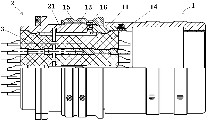
[0031] Specific embodiments of the connector assembly of the present invention, such as figure 1 As shown, the connector assembly includes a plug connector 1 and a receptacle connector 2. The two connectors are plugged and matched with each other to realize the conduction of the wire harness at both ends. The connector assembly in this embodiment is an electrical connector assembly, and the wire harness transmission is electric signal.

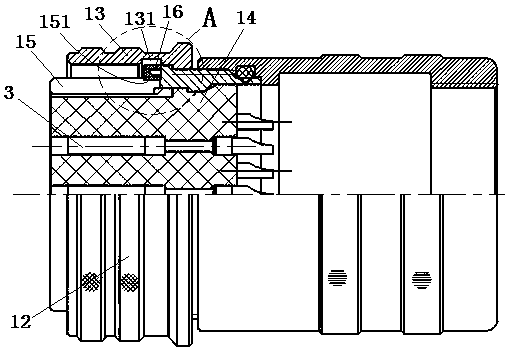
[0032] like figure 2 , 3 As shown, the plug connector 1 includes a plug housing 11, the plug end 12 of the plug housing 11 is encapsulated with a contact 3 through an insulator 14, and the contact 3 is used for mating with the contact 3 on the receptacle connector 2. catch. The insulator 14 extends out of the plug housing 11 and extends to one side of the plugging direction. The socket end 12 of the plug housing 11...


PUM


Abstract

The invention relates to a circular connector and a connector assembly. The connector assembly comprises a plug connector and a socket connector, wherein the plug connector comprises a plug shell, theperiphery of the plug shell is rotatably assembled with a connecting sleeve, the plug connector further comprises a plugging end which is mutually plugged with the socket connector, the inner circumferential surface of the plugging end is provided with a rotation-stopping spline, the periphery of the rotation-stopping spline is provided with a sealing ring, and the inner circumferential surface of the connecting sleeve is provided with an annular groove used for providing a radial deformation space for the sealing ring when the sealing ring is axially extruded by the front end face of the plugging end of the socket connector at the position corresponding to the sealing ring. The annular groove enables the sealing ring to have an enough large deformation space when being subjected to the axial extrusion and radial deformation of a socket shell. Meanwhile, the sealing ring in the gap will not be damaged because the gap between the inner wall of the connecting sleeve and the spline is too small when the connecting sleeve is screwed, and the service life of the sealing ring is prolonged. The resistance of the screwing is enabled to be reduced, and the screwing is more labor-saving.

Description

technical field [0001] The invention relates to a circular connector and a connector assembly. Background technique [0002] Circular connectors are generally required to have sealing, anti-vibration, anti-loosening and other characteristics, so that they can be used in aviation, aerospace, weapons, logging and other fields. The circular plug connector and the circular socket connector are generally locked and connected through the connecting sleeve after mating. The connecting sleeve is rotatably assembled on the plug connector housing. In the mating space for inserting the plug end of the socket connector, the outer peripheral surface of the plug end of the plug connector is also provided with anti-rotation splines for anti-rotation cooperation with the plug end of the socket connector. In order to achieve the sealing of the socket connector and the socket connector, a sealing ring is generally installed on the outer periphery of the plug end of the plug connector. After ...

Claims


Application Information

Patent Timeline
Patent Type & Authority Applications(China)
IPC IPC(8): H01R13/52H01R13/46
CPCH01R13/46H01R13/5219
Inventor 李瑶胡国闯
Owner CHINA AVIATION OPTICAL-ELECTRICAL TECH CO LTD
Why Eureka
Try Eureka