
Connector and method for electrically connecting braided shielding layer of cable to connector

A braided shielding and connector technology, which is applied to the parts, connections, circuits and other directions of the connecting device, can solve the problems of inconvenient operation, difficult to control the cutting quality of the braided shielding layer, and troublesome processing of the braided shielding layer, etc., to improve efficiency. , to ensure the effect of electromagnetic shielding effect

Pending Publication Date: 2019-01-01
TYCO ELECTRONICS (SHANGHAI) CO LTD
View PDF0 Cites 0 Cited by
  • Summary
  • Abstract
  • Description
  • Claims
  • Application Information

AI Technical Summary

Problems solved by technology

[0004] However, in the prior art, the processing of the braided shielding layer of the cable is cumbersome. It is necessary to use a cutting tool to cut off the excess length of the braided shielding layer. The operation is inconvenient and time-consuming, which will reduce the Efficiency of connecting the cable to the connector, and the quality of cutting the braided shield is difficult to control, which in turn reduces the electromagnetic shielding effectiveness of the connector

Method used

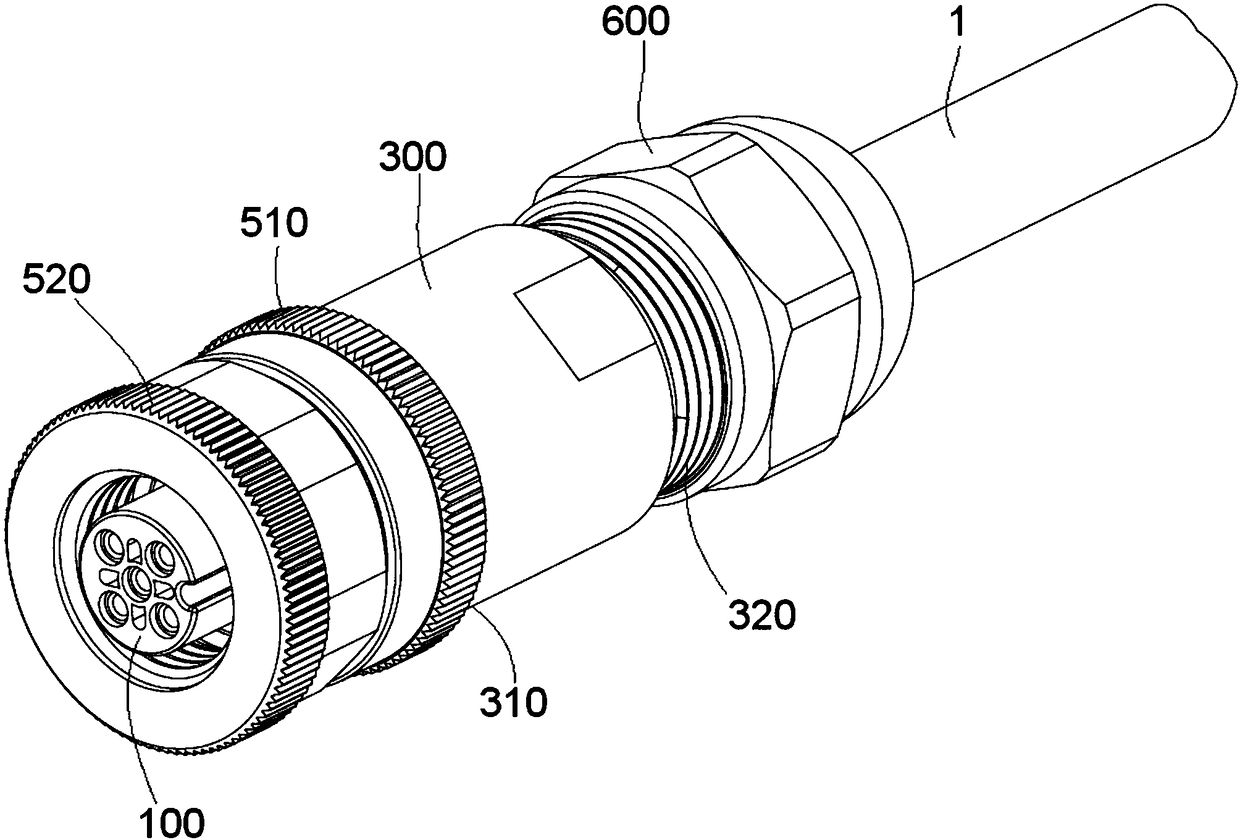
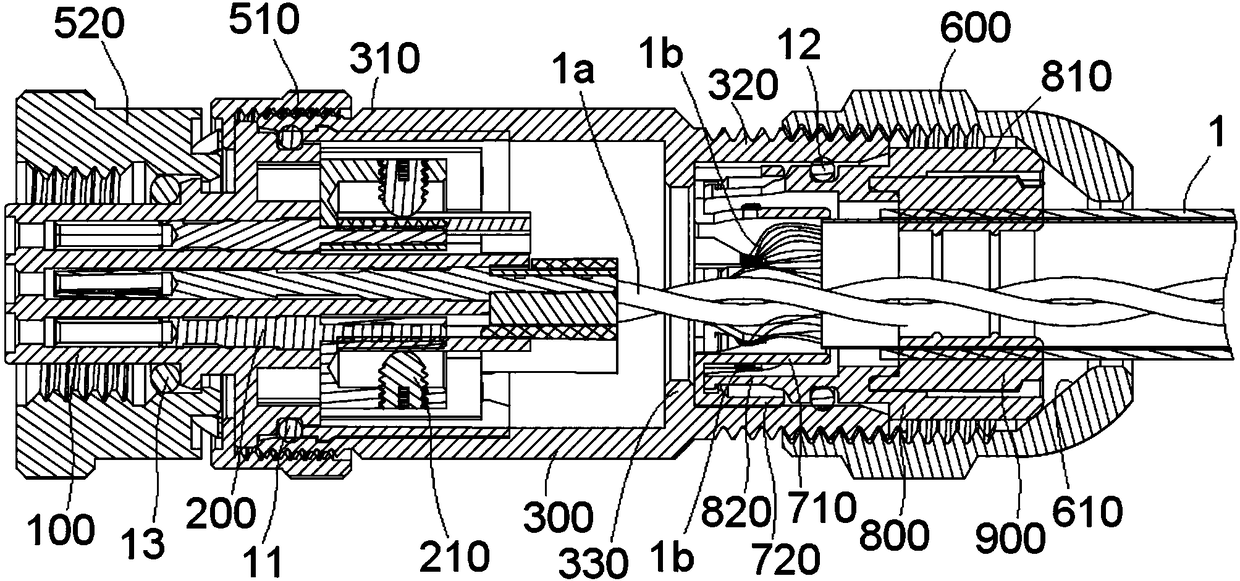
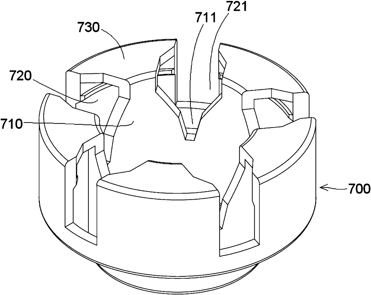

Image

  • Connector and method for electrically connecting braided shielding layer of cable to connector
  • Connector and method for electrically connecting braided shielding layer of cable to connector
  • Connector and method for electrically connecting braided shielding layer of cable to connector

Examples


Embodiment Construction

[0044] The technical solutions of the present invention will be further specifically described below through the embodiments and in conjunction with the accompanying drawings. In the specification, the same or similar reference numerals designate the same or similar components. The following description of the embodiments of the present invention with reference to the accompanying drawings is intended to explain the general inventive concept of the present invention, but should not be construed as a limitation of the present invention.

[0045]In addition, in the following detailed description, for purposes of explanation, numerous specific details are set forth in order to provide a comprehensive understanding of the embodiments of the present disclosure. It may be evident, however, that one or more embodiments may be practiced without these specific details. In other instances, well-known structures and devices are shown in diagrammatic form to simplify the drawings.

[00...


PUM


Abstract

The invention discloses a connector, which comprises a metal housing, an insulating body accommodated in the metal housing, a conductive terminal maintained in the insulating body and suitable for being electrically connected with the conductor of a cable, and a conductive shielding sleeve installed in the metal housing and electrically contacting the metal housing. The conductive shielding sleeveincludes an inner cylinder, and multiple clamp mouths are formed at the front end of the inner cylinder. The braided shielding wires of the cable are divided into multiple strands, and the multiple strands of braided shielding wires are respectively clamped in the clamp mouths and wound around the outer wall of the inner cylinder. According to the invention, the braided shielding wires of the cable are clamped in the clamp mouths of the inner cylinder of the conductive shielding sleeve, and the excessive braided shielding wires are directly wound around the inner cylinder of the conductive shielding sleeve, so that there is no need to cut off the excessive braided shielding wires. Therefore, the efficiency of connecting a cable to a connector is improved, and the electromagnetic shieldingeffect of the connector is guaranteed. The invention further discloses a method for electrically connecting the braided shielding layer of a cable to a connector.

Description

technical field [0001] The present invention relates to a connector and a method of electrically connecting a braided shield of an electrical cable to the connector. Background technique [0002] In the prior art, circular connectors used for instrumentation, control equipment and electrical equipment generally include an insulating body, conductive terminals held in the insulating body, a metal shell sleeved on the insulating body, and a metal shell mounted on the metal shell. Conductive shielding sleeve in one end. The wires of the cable can be inserted into the connector from one end of the metal shell and electrically connected with the conductive terminals in the connector. The conductive shielding sleeve is set on the braided shielding layer of the cable (usually copper wire braided shielding layer), which provides electromagnetic shielding for the cable and ensures the transmission quality of the signal. [0003] In the prior art, the conductive shielding sleeve is ...

Claims


Application Information

Patent Timeline
IPC IPC(8): H01R13/6581
CPCH01R13/6581
Inventor 余建飞潘彪汪浩张杰峰
Owner TYCO ELECTRONICS (SHANGHAI) CO LTD
Learn More