Eureka AIR delivers breakthrough ideas for toughest innovation challenges, trusted by R&D personnel around the world.

Stator core, stator, manufacturing method thereof, motor and household appliance

A stator core and stator technology, applied in the manufacture of motor generators, stator/rotor bodies, electrical components, etc., can solve the problems of increasing the effective clearance, affecting the roundness of the iron core, noise and vibration, and improving the working performance. , The effect of ensuring work performance and prolonging service life

Inactive Publication Date: 2019-01-01
GREE ELECTRIC APPLIANCES INC +1
View PDF4 Cites 2 Cited by
  • Summary
  • Abstract
  • Description
  • Claims
  • Application Information

AI Technical Summary

Problems solved by technology

This structure results in that each tooth can only be inserted into the yoke longitudinally from top to bottom or from bottom to top when splicing each other. In order to make the splicing process smooth and avoid friction between the teeth and the yoke, when splicing Usually, the gap fit method is adopted, and the existence of the gap will cause the iron core after splicing to become loose, making it difficult to ensure the roundness, which will cause noise and vibration when the motor is running, and affect the service life of the motor
In addition, the existence of the gap also increases the effective gap between the stator and the rotor, which affects the performance of the motor
In addition, the up-and-down insertion splicing method is easy to deform the interface between the tooth part and the yoke part, which will further affect the roundness of the spliced ​​iron core and affect the performance of the motor

Method used


Image

  • Stator core, stator, manufacturing method thereof, motor and household appliance
  • Stator core, stator, manufacturing method thereof, motor and household appliance
  • Stator core, stator, manufacturing method thereof, motor and household appliance

Examples


no. 1 example

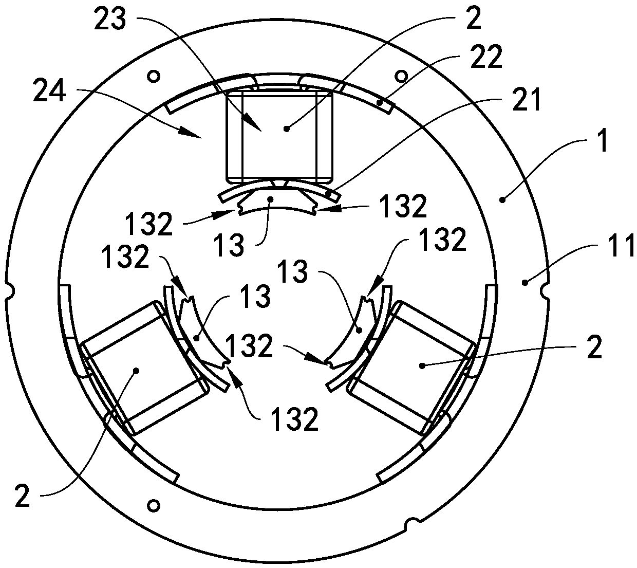
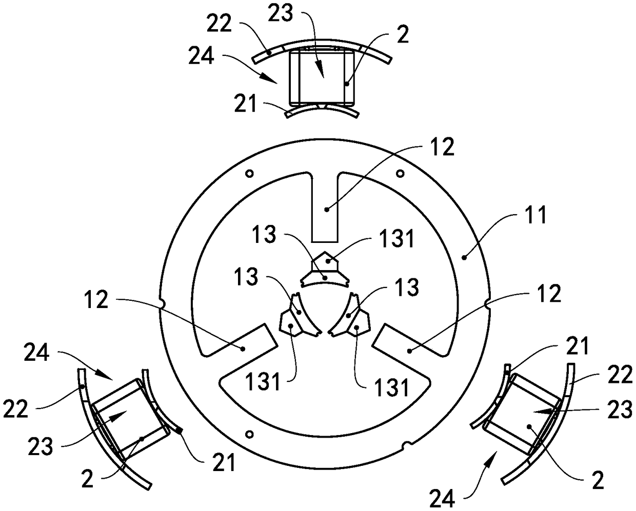
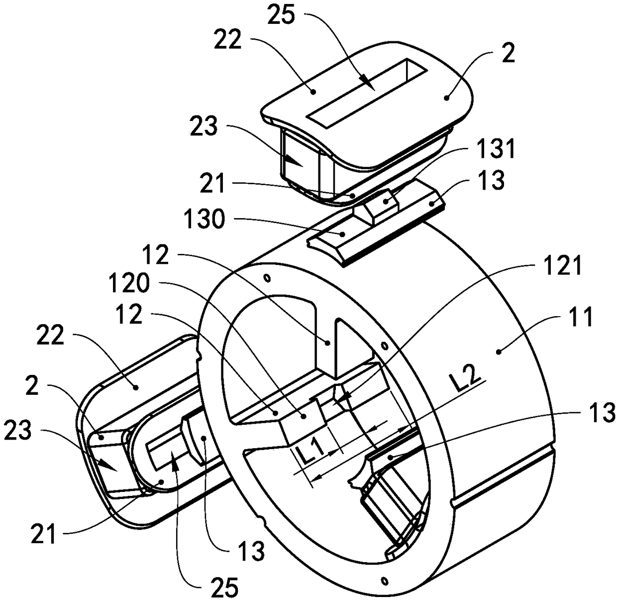
[0052] see Figure 1 to Figure 3 , The stator of this embodiment includes a stator core 1, an insulating frame 2 and a winding coil. The insulating framework 2 wraps the outside of the stator core 1 , and the winding coils are wound on the insulating framework 2 .

[0053] The stator core 1 includes a yoke 11, a plurality of teeth 12 and a plurality of boots 13, the yoke 11 is in the shape of a ring, the plurality of teeth 12 are arranged along the circumferential direction of the yoke 11, and the teeth 12 are arranged along the yoke The radial direction of the portion 11 extends from the inner peripheral wall of the yoke portion 11 to a direction away from the inner peripheral wall, that is, extends toward the axial direction of the yoke portion 11, one shoe portion 11 corresponds to one tooth portion 12, and one shoe portion 13 is arranged on it On the end of the corresponding tooth portion 12 away from the yoke portion 11 , the circle surrounded by the plurality of shoe po...


PUM


Abstract

The invention provides a stator core, a stator, a manufacturing method thereof, a motor and a household appliance. The stator core comprises a yoke portion, a plurality of tooth portions and a plurality of shoe portions, wherein the plurality of tooth portions are arranged along the circumferential direction of the yoke portion, one shoe is disposed on one end of the tooth portion corresponding tothe shoe portion, wherein the one end of the tooth portion is far away from the yoke portion; at least two splicing modules are spliced to form the stator core; the shoe portions and the yoke portionare respectively located on the two splicing modules; and the splicing modules comprise a first splicing module and a second splicing module; the first splicing module and the second splicing moduleare detachably connected with each other; positioning slots are formed in one of the first splicing module and the second splicing module, and the other splicing module is provided with matching protrusions; the matching protrusions are inserted in the positioning slots; the first splicing module and the second splicing module are spliced along the radial direction of the yoke portion; and the length of the positioning slot is smaller than the length of the yoke portion along an axial direction parallel to the yoke portion. The stator core has the advantages of simple structure, convenient assembly and accurate positioning.

Description

technical field [0001] The invention relates to the field of motors, in particular to a stator core, a stator and a manufacturing method thereof, a motor and a household appliance. Background technique [0002] The yoke and teeth of the stator of the existing motor are usually integrated. When the stator winding coil is wound on the stator core, it is difficult for the equipment to realize multi-strand parallel winding and embedding. At the same time, the motor often cannot reach a higher slot. The full rate leads to lower performance of the motor, the distribution of windings in the finished product is chaotic, and the structure is not compact, which affects the quality of the finished product. [0003] The stator of the existing motor also has a structure in which the teeth and the yoke are detachable, but the teeth and the yoke of the existing stator are generally spliced ​​by cooperating with dovetail-shaped protrusions and dovetail grooves. This structure results in th...

Claims


Application Information

Patent Timeline
Patent Type & Authority Applications(China)
IPC IPC(8): H02K1/14H02K15/02
CPCH02K1/148H02K15/022H02K2213/12
Inventor 肖胜宇黄海良唐林许金鑫陈彬刘丽刚
Owner GREE ELECTRIC APPLIANCES INC
Why Eureka
Eureka Blog
Learn More