
Displaying stand for metal artwork

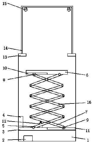
A technology of art and display stands, applied in the field of display stands, can solve the problems of unsafe handling of artworks, low practicability of display stands, and inability to protect artworks, etc., and achieve the effects of improving appreciation, convenient appreciation, and simple structure

Inactive Publication Date: 2019-01-04
吴江市一悦金属艺术品有限公司
View PDF0 Cites 2 Cited by
  • Summary
  • Abstract
  • Description
  • Claims
  • Application Information

AI Technical Summary

Problems solved by technology

[0002] With the development of society, the advancement of science and technology, and the improvement of living standards, people began to pursue the enjoyment of the spiritual level, and the observation and collection of artworks began to become popular, and the display stand is now a commonly used furnishing item when people display artworks. , for the exhibition and collection of artworks, and it is also widely used in daily life. While viewing, the requirements for the practicability of the display stands are also very high. However, the existing metal artwork display stands can be used when displaying art. , it is necessary to move the artwork back and forth, the loss of the artwork is huge during the transportation process, and it is also very unsafe to move the artwork back and forth in the exhibition hall with people coming and going, which is easy to cause damage to the artwork damage, the practicability of ordinary display stands is very low, it cannot protect artworks to a certain extent, and it cannot meet the needs of improving safety, which is far from meeting the current people's requirements for this product. Therefore, how to design A display stand for metal art, which becomes our current problem to be solved

Method used


Image

  • Displaying stand for metal artwork
  • Displaying stand for metal artwork
  • Displaying stand for metal artwork

Examples


Embodiment Construction

[0017] The present invention will be further described below in conjunction with specific embodiments, wherein, the accompanying drawings are only for exemplary illustrations, and what is shown is only a schematic diagram, rather than a physical map, and cannot be understood as a limitation to this patent. In order to better illustrate the present invention Specific embodiments, some parts in the drawings will be omitted, enlarged or reduced, and do not represent the size of the actual product. For those skilled in the art, it is understandable that some known structures and their descriptions in the drawings may be omitted. Based on The specific implementation modes in the present invention and all other specific implementation modes obtained by persons of ordinary skill in the art without making creative efforts all belong to the protection scope of the present invention.

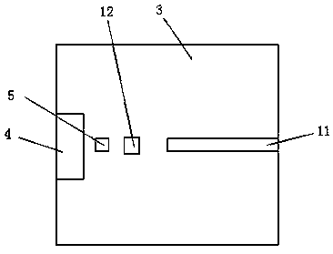
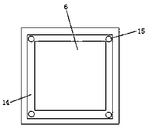
[0018] see Figure 1-Figure 3 , the present invention provides a technical solution: a display stand f...


PUM


Abstract

The invention discloses a displaying stand for metal artwork, including a base. A storage battery is arranged at that bottom of the inner chamber of the base, a horizontal support plate is arranged above the battery, and the horizontal support plate is connected to the top of the base, the left side of that top of the horizontal support plate is provided with a hot blower, a first lifting rod group is arranged on that right side of the hot blower, A low end of that lifting rod group is rotatably connected with a horizontal support plate, A top end of the lifting rod group is rotatably connected with a storage panel, a second lifting rod group is arranged on that right side of the first lifting rod group, and the first lifting rod group and the second lifting rod group are movably connectedthrough a rotating shaft. The displaying stand for metal artwork has novel structure, strong practicability, moisture-proof and corrosion-proof property, and is easy to control. A hot blow is arranged to dry that inn cavity of the display table, prevent the air humidity inside the display table from being too high, facilitate the storage of the artwork, control the height of the display panel, and is convenient for people to appreciate, and has a wide application prospect.

Description

technical field [0001] The invention relates to the technical field of display stands, in particular to a display stand for metal artworks. Background technique [0002] With the development of society, the advancement of science and technology, and the improvement of living standards, people began to pursue the enjoyment of the spiritual level, and the observation and collection of artworks began to become popular, and the display stand is now a commonly used furnishing item when people display artworks. , for the exhibition and collection of artworks, and it is also widely used in daily life. While viewing, the requirements for the practicability of the display stands are also very high. However, the existing metal artwork display stands can be used when displaying art. , it is necessary to move the artwork back and forth, the loss of the artwork is huge during the transportation process, and it is also very unsafe to move the artwork back and forth in the exhibition hall ...

Claims


Application Information

Patent Timeline
Patent Type & Authority Applications(China)
IPC IPC(8): A47F3/00A47F5/10A47F7/00A47F11/10F21V33/00
CPCA47F3/001A47B2220/0077A47F3/004A47F3/005A47F5/10A47F7/00A47F11/10F21V33/0012
Inventor 肖会东
Owner 吴江市一悦金属艺术品有限公司
Learn More