Granulating machine

A granulator and machine base technology, applied in the direction of mold extrusion granulation, etc., can solve the problems of pressure roller or ring die damage, low production efficiency, easy blockage, etc., to achieve long service life, high production rate, extrusion The effect of small pressure resistance

Pending Publication Date: 2019-01-04
WUXI VOCATIONAL & TECHN COLLEGE +1
View PDF3 Cites 2 Cited by
  • Summary
  • Abstract
  • Description
  • Claims
  • Application Information

AI Technical Summary

Problems solved by technology

Its disadvantages: the two pressure rollers of the pressure roller ring die granulator are pressed from the inside to the outside at the same time, and the ring mold is stressed from the inside to the outside, which is easy to crack and damage; the pressure roller and the ring mold slide relatively, and the material is easy to be blocked in the pressure roller Between the ring die and the ring die, the load is heavy, and the main parts such as the pressure roller, the pressure roller shaft, and the ring die are under great stress, and the temperature rises, and they will be damaged after a period of use; the power consumption of the motor is high, the output is low, and the energy consumption is high; because The pressure roller should be sealed in a cavity including the ring die, etc., and the lubricating oil hole is on the pressure roller shaft. It is very inconvenient to open the cavity when adding lubricating oil; at the same time, because the temperature of the parts is high, it is necessary to When adding lubricating oil, it needs to stop when adding lubricating oil, so the production efficiency is low
In addition, the distance between the pressure roller and the ring die is fixed, if hard impurities enter between the pressure roller and the ring die, it will also cause damage to the pressure roller or the ring die

Method used


Image

  • Granulating machine
  • Granulating machine
  • Granulating machine

Examples


Embodiment 1

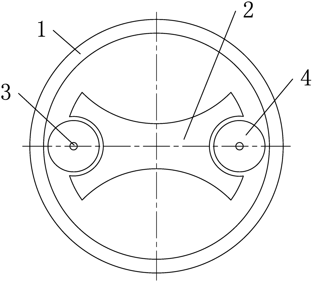
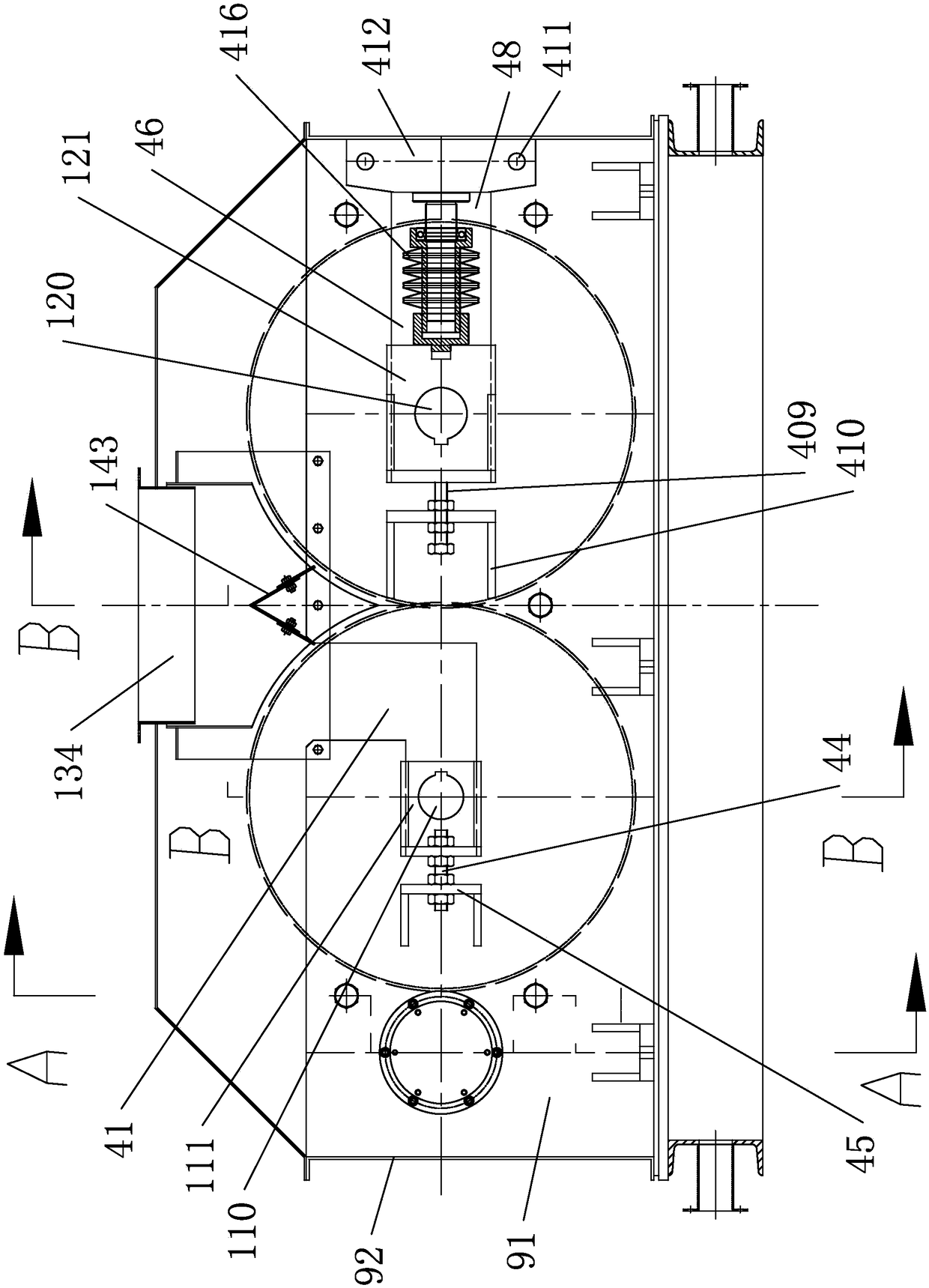
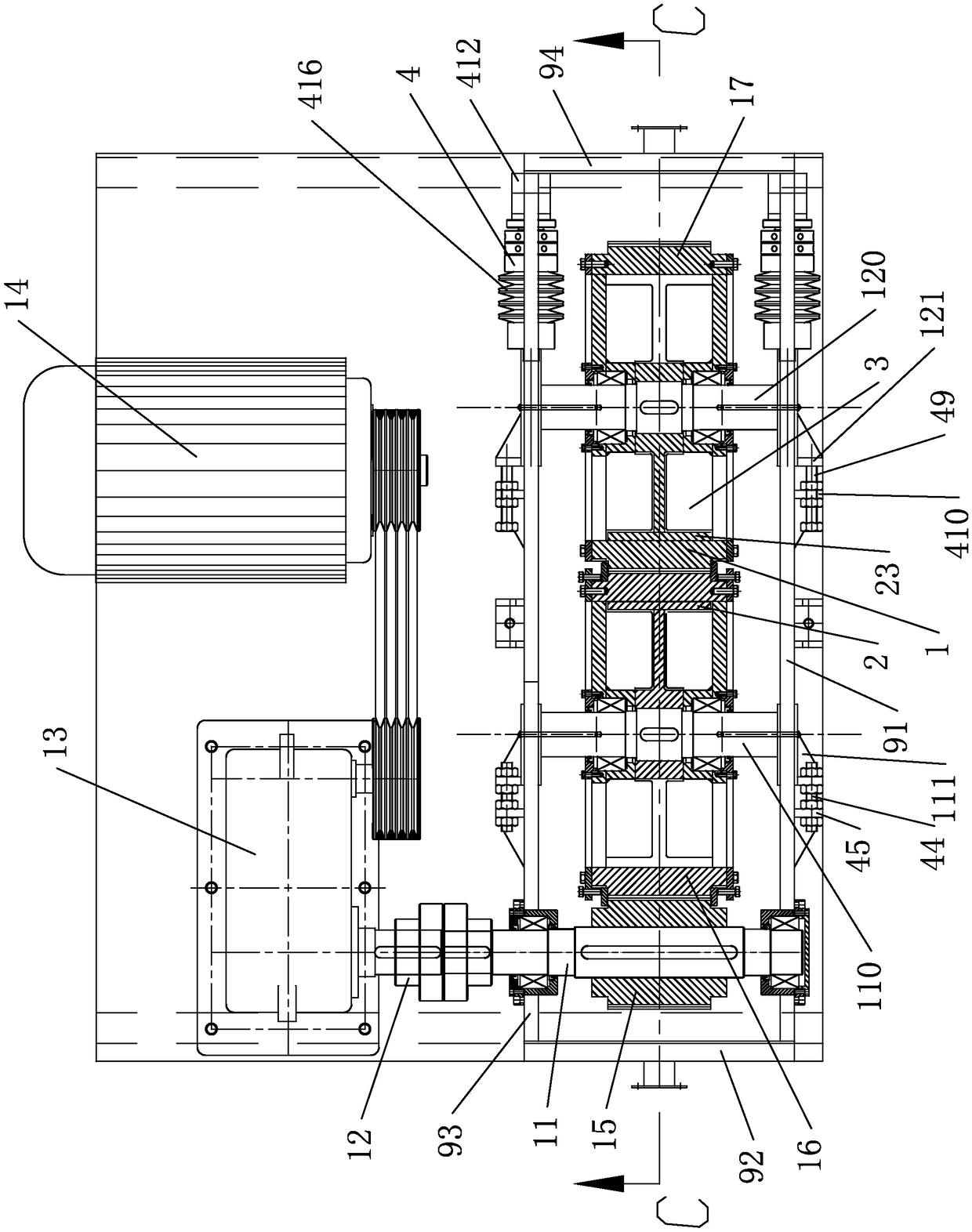
[0056] see Figure 2-6 The gear ring die granulator shown includes a machine base 9, a granulation device 1, a horizontal cutter device 2 or a directional cutter device 5, a discharge device 3, a translation device 4, and the like.

[0057] The base 9 mainly includes a cuboid working space surrounded by a front plate 91, a rear plate 93, a left plate 92, and a right plate 94, a base 95 and the like.

[0058] 1. Granulating device

[0059] see Figure 7-10 , The granulating device 1 is mainly composed of the main gear shaft 11, the main gear ring die 16, the pinion ring die 17, the hub 19, 119, the spokes 18, 118 and so on.

[0060] The main gear shaft 11 is rotatably arranged on the front plate 91 and the rear plate 93 through bearings. The main gear shaft 11 is connected with the output shaft of the speed reducer 13 through a shaft coupling 12, and the speed reducer and the motor 14 are driven by a belt.

[0061] There are two gear ring dies, namely main gear ring die 16 ...


PUM


Abstract

The invention provides a granulating machine with small stress of parts such as a ring die, stable load, long service life, low energy consumption, high yield and high production efficiency. The granulating machine comprises a machine base; two engaged gear ring dies are rotatably arranged on gear ring die shafts; one of the two gear ring die shafts is a fixed shaft, and the other one of the two gear ring die shafts is a floating shaft; the fixed shaft is fixed on the machine base; the floating shaft capable of moving relative to the fixed shaft in the radial direction is arranged on the machine base; an elastic component is arranged between the machine base and the floating shaft; a power mechanism for driving one gear ring die to rotate is arranged on the machine base; a die hole extending along a radial direction is formed in the each gear ring die; an inlet and an outlet of the die hole are formed in an outer ring and an inner ring of each gear ring die; a feeding channel is formedin the machine base; an outlet of the feeding channel is positioned on an engaged part of the outer rings of the two gear ring dies; and materials which enter from the feeding channel are pressed into the die hole by the two engaged gear ring dies from the die hole inlet and form material rods to come out of the die hole.

Description

technical field [0001] This technology relates to pelletizers, which are used to compress crushed feed, biomass pellets, etc. into high-density rods. Background technique [0002] Existing pressure roller ring die pellet mill, see figure 1 , including a ring die 1 fixed on the machine base, and a die hole is opened radially on the ring die; a rotating main shaft 2 is arranged in the ring die, and a pressure roller shaft 3 is fixedly arranged on both sides of the main shaft, and two pressure rollers 4 They are respectively arranged on the pressure roller shaft 3 through bearing rotation. There are lubricating oil holes for lubricating the bearings on the pressure roller shaft. The outer peripheral surface of the pressure roller is inscribed with the inner peripheral surface of the ring die. When the main shaft rotates, the pressure roller always moves along the inner peripheral surface of the ring die, and the crushed material entering the inner ring of the ring die is pre...

Claims


Application Information

Patent Timeline
Patent Type & Authority Applications(China)
IPC IPC(8): B01J2/22
CPCB01J2/22
Inventor 杨海霞许建东
Owner WUXI VOCATIONAL & TECHN COLLEGE
Why Eureka
Try Eureka