Metal workpiece processing method embedded with preform

A processing method and technology for metal workpieces, applied in 3D printing-related fields, can solve problems such as cracking, pipe blockage, and low dimensional accuracy in complex local areas, and achieve the effects of widening the range of material selection, optimizing manufacturing accuracy, and improving printing efficiency

Active Publication Date: 2019-01-04
HUAZHONG UNIV OF SCI & TECH
View PDF6 Cites 7 Cited by
  • Summary
  • Abstract
  • Description
  • Claims
  • Application Information

AI Technical Summary

Problems solved by technology

[0005] Aiming at the above defects or improvement needs of the prior art, the present invention provides a metal workpiece processing method embedded in prefabricated parts, wherein by combining traditional processing technology with 3D printing technology, traditional processing technology is used to manufacture high dimensional accuracy and shape Complicated internal pipelines and local areas, combined with 3D printing technology to produce shaped workpieces, can effectively solve the problems of internal pipeline blockage, cracking, and low dimensional accuracy in complex local areas; in particular, compared with existing technologies, using The invention can extend the existing laser selective melting 3D printing technology to the arc fuse additive manufacturing technology, which can improve the printing efficiency while ensuring the manufacturing accuracy, reduce the printing cost, and expand the selection range of printing materials, so it is especially suitable for Manufacture workpieces with complex internal piping and / or complex localized areas

Method used


Image

  • Metal workpiece processing method embedded with preform
  • Metal workpiece processing method embedded with preform
  • Metal workpiece processing method embedded with preform

Examples


Embodiment 1

[0057] Fig. 4 is a schematic diagram of the manufacturing process of an injection mold with a conformal cooling water channel without dividing the matrix region, wherein Figure 4a 3D model for the conformal cooling channel as a prefab, Figure 4b For an injection mold with conformal cooling channels, the specific steps are as follows:

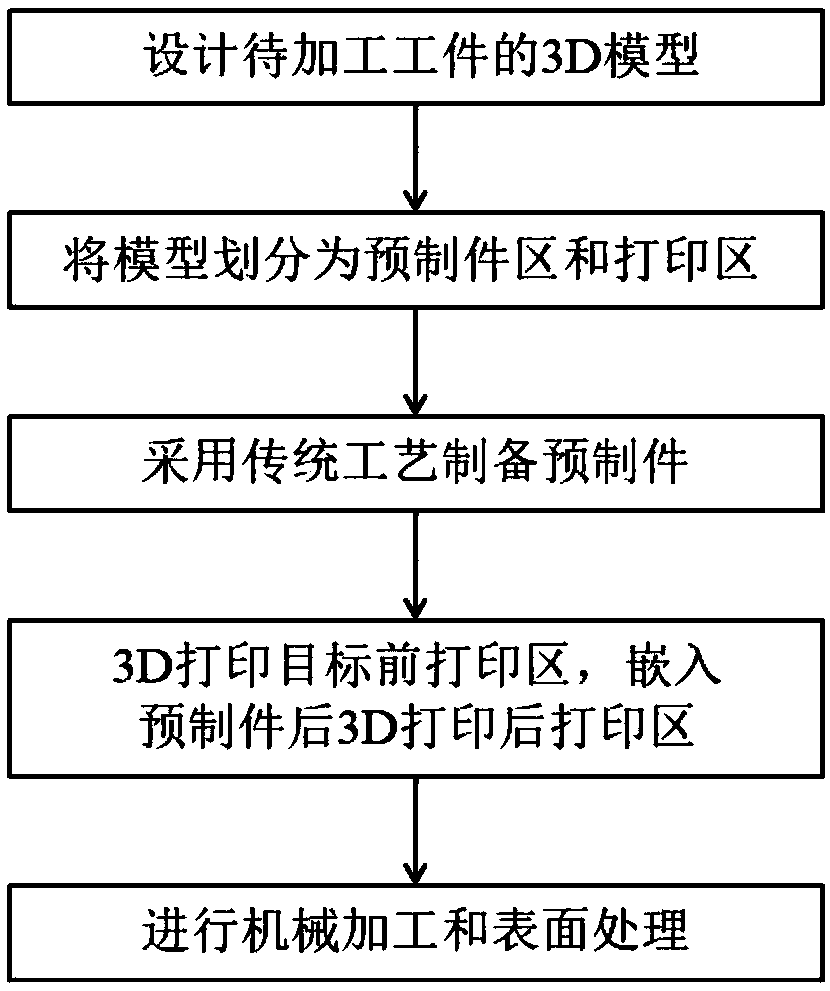
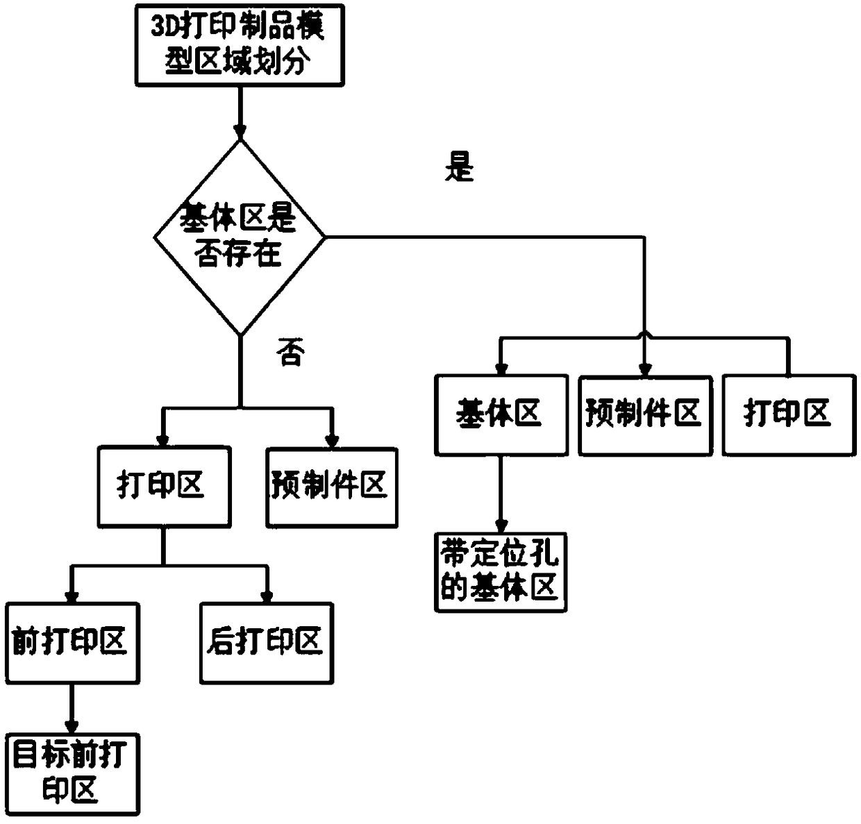
[0058] (1) First design the model of the mold, and divide the model into a prefabricated part area and a printing area. Then divide the printing area into a front printing area smaller than the height of the plane where the preform is located and a rear printing area greater than the height of the plane where the preform is located, and design a positioning groove on the model of the front printing area to obtain the target front printing area;

[0059] (2) Select a suitable molding process to prepare the prefabricated part according to the geometric dimensions and structural features of the prefabricated part; in this embodiment, for the co...

Embodiment 2

[0065] Fig. 5 is a schematic diagram of the manufacturing process of a stamping punch with a conformal cooling channel divided into a matrix area, wherein Figure 5a It is a conformal cooling channel preform fixed on the base plate, Figure 5b To form a stamping punch with a conformal cooling channel, the specific steps are as follows:

[0066] (1) First design the model of the stamping punch, and divide the model area into three parts: the matrix area, the prefabricated part area and the printing area.

[0067] (2) First, according to the geometric dimensions and structural characteristics of the conformal cooling water channel prefabricated part, an appropriate molding process is selected to prepare the conformal cooling water channel prefabricated part; The base area of ​​the mould, and two positioning holes are machined on the base plate for positioning the conformal cooling water channel preform; the diameter of the positioning holes is slightly larger than the diameter ...


PUM


Abstract

The invention belongs to the technical field of 3D printing and relates to a metal workpiece processing method embedded with a preform. The method includes the following steps: firstly, a model of theworkpiece is designed, and a proper internal pipe is designed; then the model is divided into a preform area and a printing area, and the preform is prepared by traditional technology. 3D printing isadopted to process a pre-printing area of the target, and a post-printing area is processed after the perform is embedded; at last, the workpiece with a complex inner pipe and/or a complex local areais obtained by mechanical processing and surface treatment. The invention adopts the traditional processing technology to preset the internal pipeline in advance, thus avoiding the problems of blockage and cracking of the internal pipeline, etc. The local complex area of the mould is prepared by the traditional machining technology through the way of preform, which not only ensures the manufacturing precision of the mould, but also optimizes the performance of the local area. In addition, the 3D printing method of the invention has a wide range and good adaptability. The manufacturing cost can be effectively reduced and the production efficiency can be improved by partition manufacturing.

Description

technical field [0001] The invention belongs to the technical field related to 3D printing, and more specifically relates to a method for processing metal workpieces embedded in prefabricated parts. Background technique [0002] The traditional mold cooling water channel is mainly manufactured by machining, and the internal network of straight pipes is produced by cross-drilling. However, the shape of this water channel network is quite limited. When the shape of the part is complex, the part will be deformed due to poor cooling effect. Big. The shape of the cooling water channel changes with the shape of the part, which can well solve the problem of inconsistent distance between the cooling water channel and the surface of the mold cavity, so that the parts can be cooled evenly and the cooling efficiency is higher. At present, 3D printing technology is mainly used to prepare such workpieces with complex internal pipelines, such as molds with conformal cooling channels or r...

Claims


Application Information

Patent Timeline
Patent Type & Authority Applications(China)
IPC IPC(8): B22F3/105B22F7/08B33Y10/00B33Y50/02B33Y80/00
CPCB22F7/08B33Y10/00B33Y50/02B33Y80/00B22F10/00B22F12/70B22F10/66B22F12/88B22F10/25B22F10/64B22F10/28Y02P10/25
Inventor 郑志镇龙平李建军余圣甫
Owner HUAZHONG UNIV OF SCI & TECH
Why Eureka
Try Eureka