A Control Method of Rigid-Flexible Coupling Motion Platform Based on Disturbance Force Compensation

A control method, rigid-flexible coupling technology, applied in the direction of program control manipulators, manufacturing tools, manipulators, etc., can solve the problems that it is difficult to meet the needs of high-speed precision motion control, LADRC cannot adapt to high bandwidth requirements, and the control process is complicated, etc., to achieve reduced control Complexity, avoiding noise, and achieving high-speed precision motion effects

Active Publication Date: 2021-03-09
FOSHAN HUADAO SUPER PRECISION TECH CO LTD
View PDF10 Cites 0 Cited by
  • Summary
  • Abstract
  • Description
  • Claims
  • Application Information

AI Technical Summary

Problems solved by technology

Traditional friction compensation schemes and control methods are difficult to meet the growing demand for high-speed precision motion control
In order to solve the above problems, scientists in this field have been working hard to find a control scheme that can overcome frictional disturbances. Among them, the linear active disturbance rejection control algorithm (LADRC) is an effective method to overcome disturbances. Unified consideration, this can suppress the disturbance to a certain extent, but some scientific researchers have found that LADRC is not suitable for high bandwidth requirements and strong nonlinearity caused by friction (dead zone etc.)
At the same time, the previous technology uses a frictionless flexible hinge combined with a mechanical guide rail platform to realize the compensation of the friction dead zone. However, due to the inconsistency between the high-speed motion and the control law of the compensation process, model switching control is required, but the model switching control makes the whole The control process becomes complex and cumbersome

Method used


Image

  • A Control Method of Rigid-Flexible Coupling Motion Platform Based on Disturbance Force Compensation
  • A Control Method of Rigid-Flexible Coupling Motion Platform Based on Disturbance Force Compensation
  • A Control Method of Rigid-Flexible Coupling Motion Platform Based on Disturbance Force Compensation

Examples


Embodiment 1

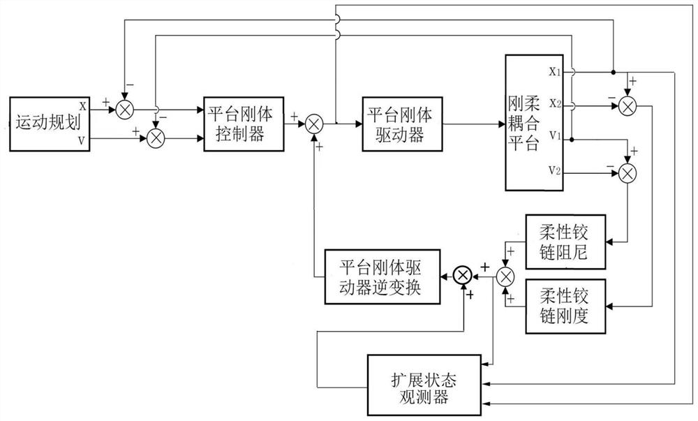
[0048] like figure 1 As shown, in the embodiment of the present invention, the rigid-flexible coupling platform mainly includes a mechanical guide rail, a frame rigid body, a flexible hinge, and a platform rigid body. M ,X m are the displacements of the frame rigid body and the platform rigid body, respectively, are the velocities of the frame rigid body and the platform rigid body, respectively, M, m are the mass of the frame rigid body and the platform rigid body, respectively, k, c are the stiffness and damping of the flexible hinge, F M ,F m are the driving force of the driving unit acting on the frame rigid body and the platform rigid body, respectively, f μ is the friction force between the frame rigid body and the mechanical guide rail.

[0049] The rigid-flexible coupled motion platform control method based on disturbance force compensation in this embodiment is single-drive motion control, and the mechanical response equation of the platform rigid body motion is:...

Embodiment 2

[0072] like Figure 8 As shown, in the embodiment of the present invention, the rigid-flexible coupling platform mainly includes a mechanical guide rail, a frame rigid body, a flexible hinge, and a platform rigid body. M ,X m are the displacements of the frame rigid body and the platform rigid body, respectively, are the velocities of the frame rigid body and the platform rigid body, respectively, M, m are the mass of the frame rigid body and the platform rigid body, respectively, k, c are the stiffness and damping of the flexible hinge, F M ,F m are the driving force of the driving unit acting on the frame rigid body and the platform rigid body, respectively, f μ is the friction force between the frame rigid body and the mechanical guide rail.

[0073] The control method of the rigid-flexible coupled motion platform based on disturbance force compensation in this embodiment is dual-drive motion control, wherein the mechanical response equation of the rigid body motion of...


PUM


Abstract

The invention discloses a rigid-flexible coupling motion platform control method based on disturbance force compensation. The method includes the steps that firstly, the speed and displacement of a platform rigid body serve as feedback, a driving unit of the platform rigid body is an actuator, and a closed-loop control system of the platform rigid body is established; then the speed and displacement of a frame rigid body are detected, and the difference between the speed of the frame rigid body and the speed of the platform rigid body and the difference between the displacement of the frame rigid body and the displacement of the platform rigid body are obtained respectively; then the obtained speed difference and the displacement difference are multiplied by the damping and the rigidity ofa flexible hinge respectively, the measuring disturbance force of the flexible hinge on the platform rigid body is obtained, a control signal and the measuring disturbance force are input into an expansion observer, and estimation of rest disturbance is obtained; finally, the obtained sum of the measured disturbance and the estimated disturbance is converted into the equivalent control amount according to a transfer function of the control quantity to the driving force, and the equivalent control amount is compensated into the control amount of the platform rigid body and converted into a rigid body platform control system free of disturbance. Compared with the prior art, the technical scheme does not need switching control, the control complexity is reduced, and finally, the high-speed precise motion is realized.

Description

technical field [0001] The invention relates to the technical field of high-speed precision motion control, in particular to a rigid-flexible coupling motion platform control method based on disturbance force compensation. Background technique [0002] In the field of high-speed precision motion control, there is a friction dead zone in the motion platform based on mechanical guide rails, so the control accuracy can only reach the micron level. In the case of higher precision control, it is necessary to use air suspension, magnetic suspension or static pressure guide rail to reduce or even eliminate the friction effect. A wide range of electronic manufacturing technology fields. [0003] Moore's law exists in the electronics manufacturing industry, that is, when the price does not change, the number of components that can be accommodated on an integrated circuit will double every 18 to 24 months, and the performance will also double. The accuracy and speed of the system pu...

Claims


Application Information

Patent Timeline
Patent Type & Authority Patents(China)
IPC IPC(8): B25J9/16
CPCB25J9/1605B25J9/161
Inventor 杨志军曾丹平黄瑞锐李艳龙潘加键
Owner FOSHAN HUADAO SUPER PRECISION TECH CO LTD
Why Eureka
Try Eureka