A Control Method of Rigid-Flexible Coupling Motion Platform Based on Disturbance Force Measurement and Compensation

A control method, rigid-flexible coupling technology, applied in electric controllers, controllers with specific characteristics, adaptive control, etc., can solve the problems that LADRC cannot apply to high bandwidth requirements, is cumbersome, and is difficult to meet the needs of high-speed precision motion control , to achieve the effect of reducing the control complexity

Active Publication Date: 2021-08-24
GUANGDONG UNIV OF TECH
View PDF2 Cites 0 Cited by
  • Summary
  • Abstract
  • Description
  • Claims
  • Application Information

AI Technical Summary

Problems solved by technology

Traditional friction compensation schemes and control methods are difficult to meet the growing demand for high-speed precision motion control
In order to solve the above problems, scientists in this field have been working hard to find a control scheme that can overcome frictional disturbances. Among them, the linear active disturbance rejection control algorithm (LADRC) is an effective method to overcome disturbances. Unified consideration, this can suppress the disturbance to a certain extent, but some scientific researchers have found that LADRC is not suitable for high bandwidth requirements and strong nonlinearity caused by friction (dead zone etc.)
At the same time, the previous technology uses a frictionless flexible hinge combined with a mechanical guide rail platform to realize the compensation of the friction dead zone. However, due to the inconsistency between the high-speed motion and the control law of the compensation process, model switching control is required, but the model switching control makes the whole The control process becomes complex and cumbersome

Method used


Image

  • A Control Method of Rigid-Flexible Coupling Motion Platform Based on Disturbance Force Measurement and Compensation
  • A Control Method of Rigid-Flexible Coupling Motion Platform Based on Disturbance Force Measurement and Compensation
  • A Control Method of Rigid-Flexible Coupling Motion Platform Based on Disturbance Force Measurement and Compensation

Examples


Embodiment 1

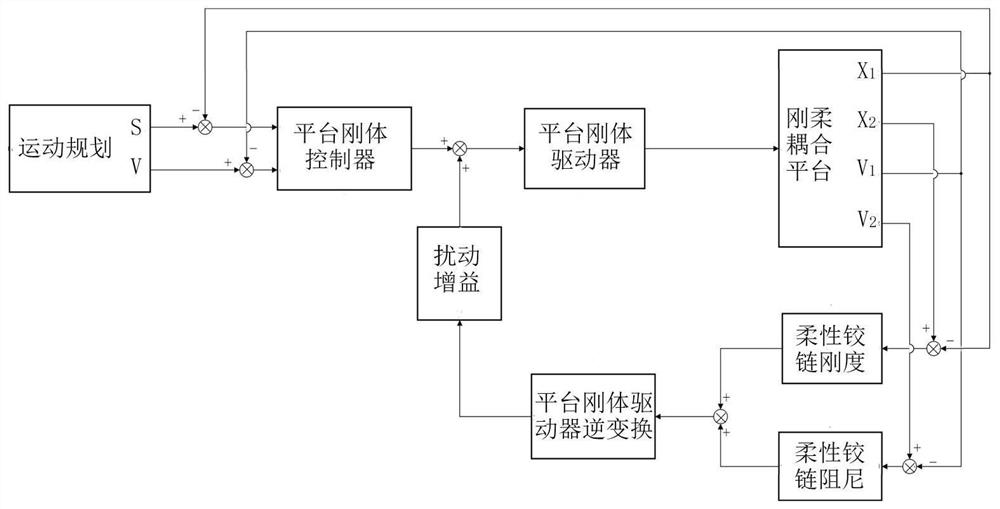
[0043] In the embodiment of the present invention, the rigid-flexible coupling platform mainly includes a mechanical guide rail, a frame rigid body, a flexible hinge, and a platform rigid body. Set X M ,X m are the displacements of the frame rigid body and the platform rigid body, respectively, are the velocities of the frame rigid body and the platform rigid body respectively, M and m are the masses of the frame rigid body and the platform rigid body respectively, k and c are the stiffness and damping of the flexible hinge respectively, F M , F m are the driving force of the driving unit acting on the frame rigid body and the platform rigid body respectively, f μ is the friction force between the frame rigid body and the mechanical guide rail.

[0044]The rigid-flexible coupled motion platform control method based on disturbance force measurement and compensation in this embodiment is single-drive motion control, where the mechanical response equation of the rigid body mo...

Embodiment 2

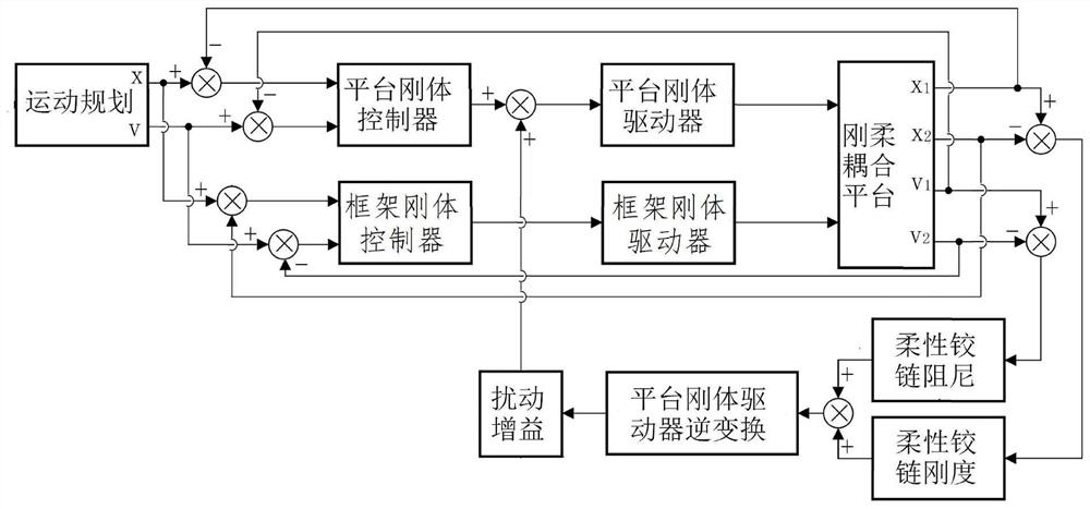
[0056] In the embodiment of the present invention, the rigid-flexible coupling platform mainly includes a mechanical guide rail, a frame rigid body, a flexible hinge, and a platform rigid body. Set X M ,X m are the displacements of the frame rigid body and the platform rigid body, respectively, are the velocities of the frame rigid body and the platform rigid body respectively, M and m are the masses of the frame rigid body and the platform rigid body respectively, k and c are the stiffness and damping of the flexible hinge respectively, F M , F m are the driving force of the driving unit acting on the frame rigid body and the platform rigid body respectively, f μ is the friction force between the frame rigid body and the mechanical guide rail.

[0057] The rigid-flexible coupled motion platform control method based on disturbance force measurement and compensation in this embodiment is dual-drive motion control, where the mechanical response equation of the rigid body mot...

Embodiment 3

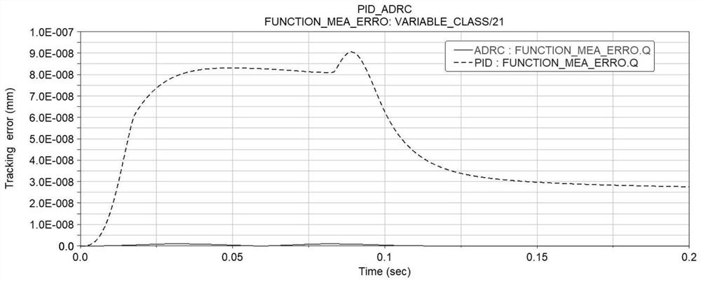
[0070] The platform parameters of this embodiment are:

[0071] Core platform quality m 2kg Frame quality M 2kg coefficient of friction 0.2 Flexible hinge stiffness k 2000N / mm Flexible hinge damping c 100N / mm / s Optimized Kp 35702280.82 Optimized Ki 7172.72 Optimized Kd 349977.10

[0072] see Figure 2 to Figure 4 , when using the traditional PID method and the ADRC method using spring damping force compensation, the position tracking error curve is compared as figure 2 As shown, the maximum error drops from 9e-8 to 9e-9, an order of magnitude reduction.

[0073] When using PID control, if the model parameters change, the tracking error will change accordingly, such as image 3 Shown, yet adopt the active disturbance rejection control (ADRC) method of the technical scheme of the present invention of spring damping force compensation, the tracking error hardly changes with the model change, shows good disturbance re...


PUM


Abstract

The invention discloses a rigid-flexible coupling motion platform control method based on disturbance force measurement and compensation. Firstly, the speed and displacement of the rigid body of the platform are used as feedback, and the driving unit of the rigid body of the platform is an actuator. A closed-loop control system of the rigid body of the platform is established, and then the frame is detected. The velocity and displacement of the rigid body are respectively compared with the velocity and displacement of the rigid body of the platform to obtain the velocity difference and displacement difference between the two, and then the obtained velocity difference and displacement difference are multiplied by the damping and stiffness of the flexible hinge respectively to obtain the The disturbance force of the flexible hinge on the rigid body of the platform is finally converted into an equivalent control quantity by dividing the obtained disturbance force by the transfer function from the control quantity to the driving force, and then multiplied by a proportional gain to compensate the control quantity of the rigid body of the platform, which is transformed into Disturbance-free rigid-body platform control system. Compared with the prior art, the technical solution of the present invention does not need switching control and reduces control complexity, and finally realizes high-speed precision motion.

Description

technical field [0001] The invention relates to the technical field of high-speed precision motion control, in particular to a rigid-flexible coupling motion platform control method based on disturbance force measurement and compensation. Background technique [0002] In the field of high-speed precision motion control, there is a friction dead zone in the motion platform based on mechanical guide rails, so the control accuracy can only reach the micron level. In the case of higher precision control, it is necessary to use air suspension, magnetic suspension or static pressure guide rail to reduce or even eliminate the friction effect. A wide range of electronic manufacturing technology fields. [0003] Moore's law exists in the electronics manufacturing industry, that is, when the price does not change, the number of components that can be accommodated on an integrated circuit will double every 18 to 24 months, and the performance will also double. The accuracy and speed ...

Claims


Application Information

Patent Timeline
Patent Type & Authority Patents(China)
IPC IPC(8): G05B13/04G05B11/42
CPCG05B11/42G05B13/042
Inventor 曾丹平黄瑞锐李艳龙潘加键杨志军
Owner GUANGDONG UNIV OF TECH
Why Eureka
Try Eureka