High-speed moving body microbubble drag reduction structure in water

A moving body, micro-bubble technology, applied in the direction of hydrodynamic characteristics/hydrostatic characteristics, hull, hull design, etc., can solve the problems of easy instability, difficult to maintain stability, limited wet area, etc. Guarantee the effect of good hydrodynamic characteristics and good maneuverability

Inactive Publication Date: 2019-01-04
HARBIN ENG UNIV
View PDF6 Cites 11 Cited by
  • Summary
  • Abstract
  • Description
  • Claims
  • Application Information

AI Technical Summary

Problems solved by technology

[0002] Although water and air are both fluids, navigating in water is not like navigating in the air. Since water is much denser than air, although it can improve greater power, it will also bring huge resistance. It is difficult for current materials to meet its strength. So far, there has not been a case of sailing in water that exceeds several times the speed of sound like an airplane, and even 0.1 times the speed of sound underwater is also very difficult. Usually, underwater high-speed flying objects are only tens of meters per second, and the technology of cavitation drag reduction appears. Especially in the last century, the Soviet Union developed the blizzard torpedo, which brought a glimmer of opportunity and dawn to underwater ultra-high-speed navigation
For underwater t

Method used


Image

  • High-speed moving body microbubble drag reduction structure in water
  • High-speed moving body microbubble drag reduction structure in water
  • High-speed moving body microbubble drag reduction structure in water

Examples


Embodiment Construction

[0013] The present invention will be further described below in conjunction with accompanying drawing;

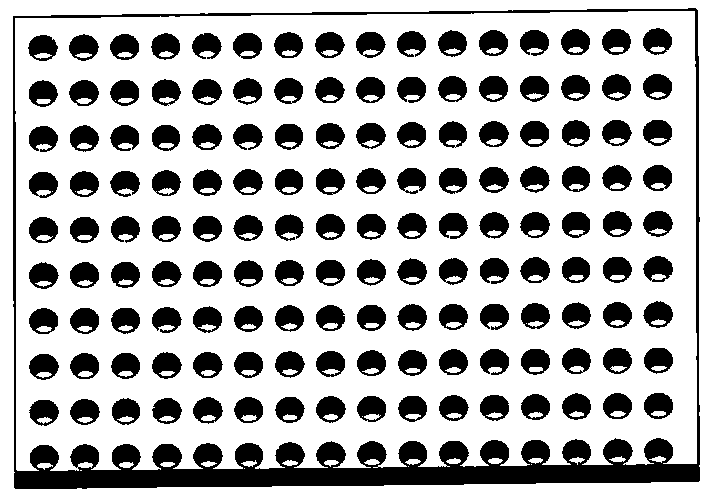
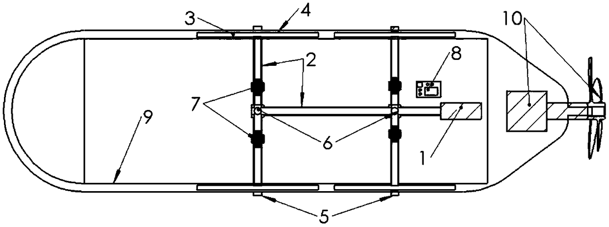
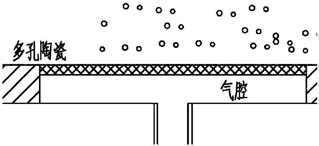
[0014] as attached figure 1 Shown, is porous ceramic diagram of the present invention, appended figure 2 It is a structural diagram of the present invention; image 3 It is a detailed diagram of the present invention; a microbubble drag reduction structure of a high-speed moving body in water, including an air pump 1, an air supply pipeline 2, an air cavity 3, porous ceramics 4, a multifunctional sensor 5, an electronic pressure regulating valve 6, and an electronic flowmeter 7 , the control equipment 8, the navigation body 9, and the power unit 10; the overall structure is symmetrical, the power unit 10 is located at the tail of the navigation body, and other devices are located inside the navigation body. There is an electronic pressure regulating valve 6 and an electronic flowmeter 7, the air chamber 3 is in close contact with the porous ceramic 4, and there is a mult...


PUM


Abstract

The invention belongs to the drag reduction field of an aircraft body, in particular to a high-speed moving body microbubble drag reduction structure in water. The structure comprises an air pump, anair supply pipeline, an air cavity, a porous ceramic, a multifunctional sensor, an electronic pressure regulating valve, an electronic flowmeter, a control device, an aircraft body and a power unit; the whole structure is symmetrical, the power device is located at the tail of the vehicle, other devices are located in the body of the vehicle, the air pump is connected with the air cavity through the air supply pipeline, the air supply pipeline is a hose, the air supply pipeline is provided with an electronic pressure regulating valve and an electronic flowmeter, the air cavity is in close contact with the porous ceramics, and the porous ceramics has a multifunctional sensor. By means of the drag reduction method of penguin-like micro-bubble group covering the surface of the vehicle, when the acceleration is needed suddenly, the wet area changes little and the manipulation performance is very good during the voyage. The mechanism designed in this paper mainly reduces the surface drag, which is not restricted by the strict size. Moreover, the application of the surface drag reduction will not destroy the original design shape of the vehicle, and can ensure the hydrodynamic characteristics.

Description

technical field [0001] The invention in this paper belongs to the field of drag reduction of flying bodies, and specifically relates to a microbubble drag reduction structure of a high-speed moving body in water. Background technique [0002] Although water and air are both fluids, navigating in water is not like navigating in the air. Since water is much denser than air, although it can improve greater power, it will also bring huge resistance. It is difficult for current materials to meet its strength. So far, there has not been a case of sailing in water that exceeds several times the speed of sound like an airplane, and even 0.1 times the speed of sound underwater is also very difficult. Usually, underwater high-speed flying objects are only tens of meters per second, and the technology of cavitation drag reduction appears. Especially in the last century, the Soviet Union developed the blizzard torpedo, which brought a glimmer of opportunity and dawn to underwater ultra-...

Claims


Application Information

Patent Timeline
IPC IPC(8): B63B1/38
CPCB63B1/38B63B2001/387Y02T70/10
Inventor 蒋运华要尧王海波邹志辉张德欣
Owner HARBIN ENG UNIV
Why Eureka
Try Eureka