Supercharge Your Innovation With Domain-Expert AI Agents!

Plastic film reel erecting device with pipe core

A plastic film and erecting device technology, which is applied in the direction of packaging material feeding device, packaging, transportation packaging, etc., can solve the problems of increasing labor intensity, occupying a large area, and laborious cutting, so as to reduce work intensity and make The effect of convenience and simple structure

Inactive Publication Date: 2019-01-04
TIANJIN TIANSU SCI & TECH GROUP
View PDF0 Cites 0 Cited by
  • Summary
  • Abstract
  • Description
  • Claims
  • Application Information

AI Technical Summary

Problems solved by technology

Because the plastic film roll is placed in a horizontal position at this time, and the weight of each roll of film is usually more than 100Kg, it is very laborious for the operator to cut it. This method not only increases the labor intensity, but also easily causes safety hazards. Large area

Method used


Image

  • Plastic film reel erecting device with pipe core
  • Plastic film reel erecting device with pipe core
  • Plastic film reel erecting device with pipe core

Examples


Embodiment 1

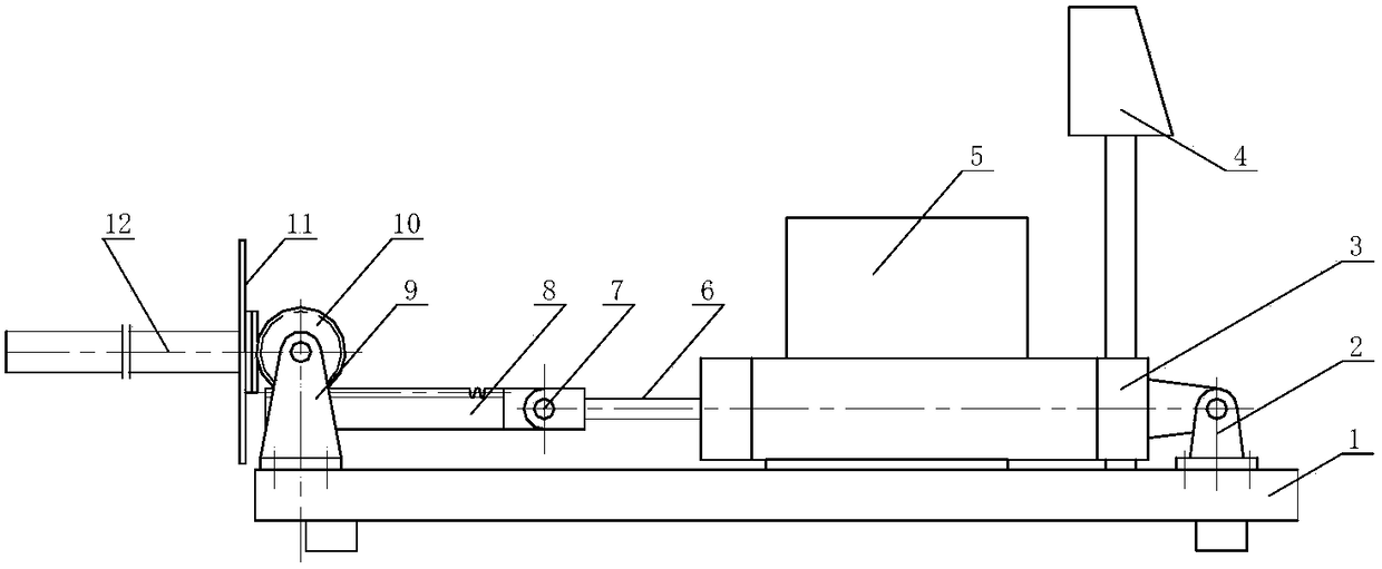
[0016] Example 1, see Figure 1-Figure 3 , a device for erecting plastic film rolls with a tube core, including a base 1 on which an electric control box 4, a hydraulic mechanism 5, an oil cylinder 3, an overturning mechanism and a transmission mechanism are arranged, and the piston of the oil cylinder The rod 6 is connected with a transmission mechanism for driving the turning mechanism to turn over through the hinge 7, and the electric control box 4 is electrically connected with the hydraulic mechanism.

[0017] In this embodiment, the hinge 7 is preferably a flexible joint.

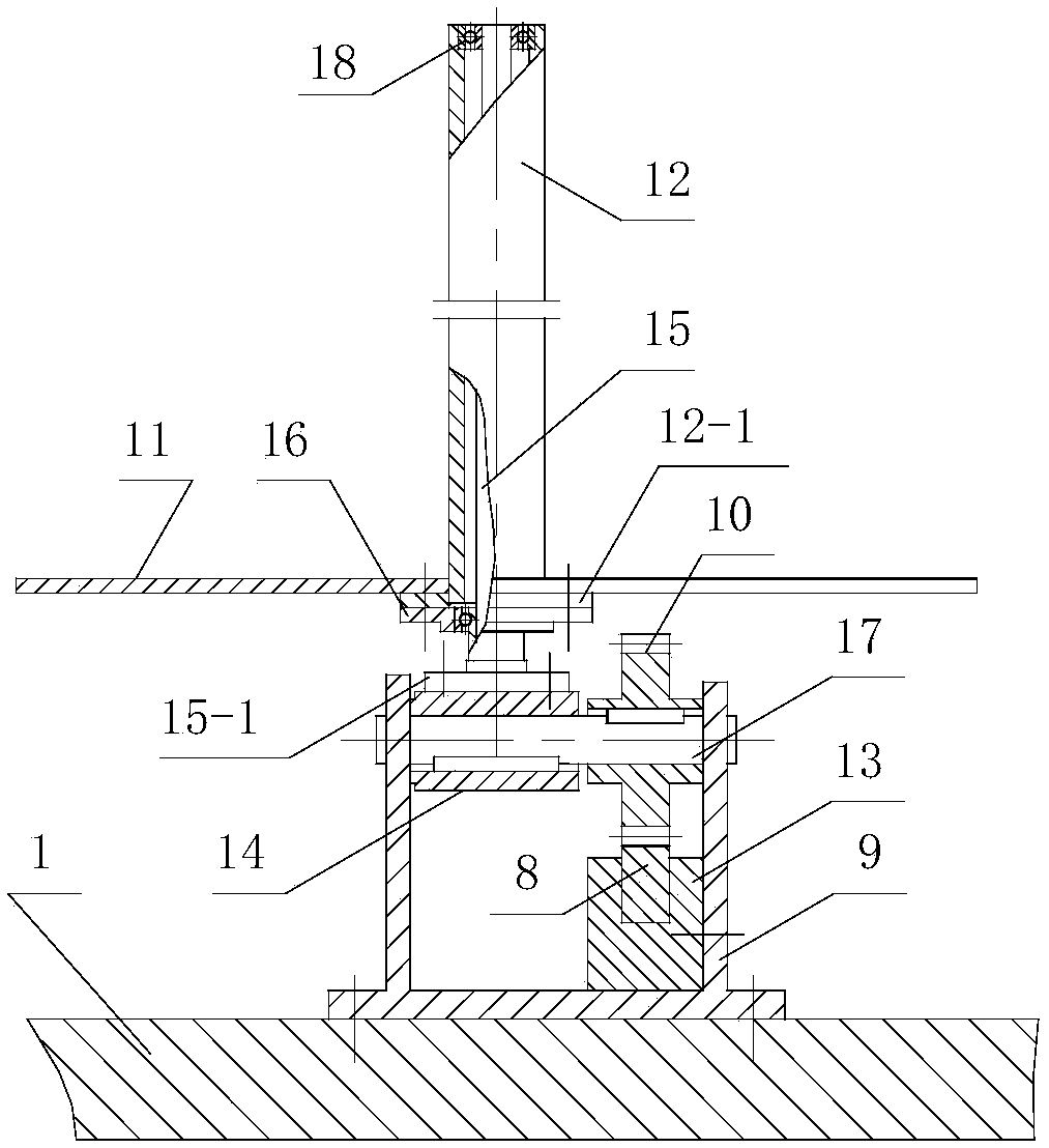
[0018] In this embodiment, the transmission mechanism includes a rack 8 connected to the piston rod of the oil cylinder, a gear bracket 9, a gear 10 and a shaft 7, the gear bracket is fixed on the base 1, and the rack is fixed on the gear The rack seat 13 on the inside of the bracket is affixed and meshed with the gear mounted on the gear bracket. Described axle 7 is installed on the gear bracket, a...

Embodiment 2

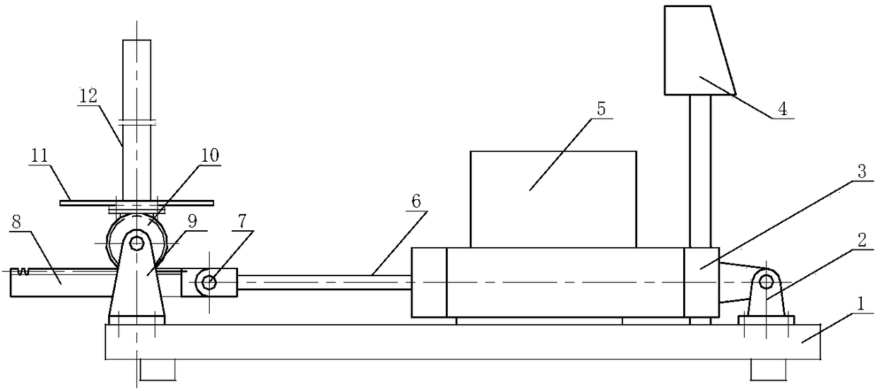
[0020] Example 2, see Figure 4 , a device for erecting plastic film rolls with tube cores, including a base 1 on which an electric control box 4, a hydraulic mechanism 5, three oil cylinders 3, three turning mechanisms and three transmission mechanisms are arranged, and the pistons of the oil cylinders The rod 6 is connected with a transmission mechanism for driving the turning mechanism to turn over through the hinge 7, and the electric control box 4 is electrically connected with the hydraulic mechanism. Both the turning mechanism and the transmission mechanism are the same as those in the embodiment, and the hydraulic mechanism needs to control each oil cylinder separately.

[0021] The erecting device of the plastic film roll with tube core is not limited to the single oil cylinder or three oil cylinders and the corresponding turning mechanism and transmission mechanism described in Embodiment 1 and Embodiment 2, but also can arbitrarily set the position of the oil cylind...


PUM

PropertyMeasurementUnit
diameteraaaaaaaaaa
lengthaaaaaaaaaa

Abstract

The invention relates to a plastic film reel erecting device with a pipe core. The plastic film reel erecting device with the pipe core is characterized by comprising a base, wherein an electric control box, a hydraulic mechanism, an oil cylinder, an overturning mechanism and a transmission mechanism are arranged on the base; a piston rod of the oil cylinder is connected with the transmission mechanism used for driving the overturning mechanism to overturn through a hinge element; and the electric control box is electrically connected with the hydraulic mechanism. The plastic film reel erecting device with the pipe core has the following advantages: through cooperation of the oil cylinder, the overturning mechanism and the transmission mechanism of the film reel erecting device, a film reel to be treated can be conveniently overturned to be in an upright state from a horizontal state only by pressing a control button on the electric control box, and in this way, the working intensity of operating personnel can be greatly reduced, and the production efficiency can be greatly increased; and meanwhile, the personal safety of the operating personnel can further be guaranteed. The device is simple in structure, convenient to produce, low in fault rate, and especially suitable for the need of erecting operation for a film reel wrapper with the film reel having a weight of 100kg and above; and moreover, the floor area is reduced.

Description

technical field [0001] The invention belongs to the technical field of plastic film processing machinery, in particular to a device for erecting plastic film rolls with tube cores. Background technique [0002] Plastic film is used more and more widely. Usually, the finished film roll needs to be wrapped with a wrapper to prevent the finished film roll from being scratched or dirty during handling. The traditional packaging skin is wound by a plastic film on the tube core, and cut according to the required length during use. Because the plastic film roll is placed in a horizontal position at this time, and the weight of each roll of film is usually more than 100Kg, it is very laborious for the operator to cut it. This method not only increases the labor intensity, but also easily causes safety hazards. Large footprint. Contents of the invention [0003] In order to solve the technical problems in the known technology, the present invention provides a plastic film roll er...

Claims


Application Information

Patent Timeline
Patent Type & Authority Applications(China)
IPC IPC(8): B65B41/12B65B61/00
CPCB65B41/12B65B61/00
Inventor 邵克明刘伟龚武忠霍金毅李帅
Owner TIANJIN TIANSU SCI & TECH GROUP
Features
  • R&D
  • Intellectual Property
  • Life Sciences
  • Materials
  • Tech Scout
  • Unparalleled Data Quality
  • Higher Quality Content
  • 60% Fewer Hallucinations
Learn More