Height-adjustable reeling system

A technology of height and lifting bracket, applied in the field of wire shaking system, can solve the problems of lack of counting function, unable to meet the needs, lack of counting device, etc., and achieve the effect of good connection and power transmission effect.

Inactive Publication Date: 2019-01-04
德清县金丝源纺织品有限公司
View PDF7 Cites 2 Cited by
  • Summary
  • Abstract
  • Description
  • Claims
  • Application Information

AI Technical Summary

Problems solved by technology

Before the yarn is sampled on the sample machine, it needs to be sorted into yarns with a certain quantity and length. The existing device for sorting the yarn for the sample machine is to manually shake a rotating rod installed on the bracket to drive The cylindrical scaffolding on the rotating rod rotates, so that the bobbin or skein is wound on the cylindrical scaffolding to obtain a certain length and quantity of yarn; however, there is a lack of counting device, and when the operator rotates the cylindrical scaffolding When the yarn is arranged, it is necessary to constantly memorize the number of rotations, which takes a lot of energy and brain power. When the number of rotations is large, human memory is prone to errors, which will cause inconvenience to subsequent operations; the bracket is a fixed frame, only It can play a limited supporting role, and cannot move flexibly according to the needs, nor can it adjust the height according to the needs of the operator, which is very rigid
[0004] Therefore, the existing device for arranging yarn for the sample machine has the problems of insufficient flexibility, lack of counting function, inconvenient movement and non-adjustable height

Method used


Image

  • Height-adjustable reeling system
  • Height-adjustable reeling system
  • Height-adjustable reeling system

Examples


Embodiment Construction

[0040] The present invention will be further described below in conjunction with the accompanying drawings and embodiments, but not as a basis for limiting the present invention.

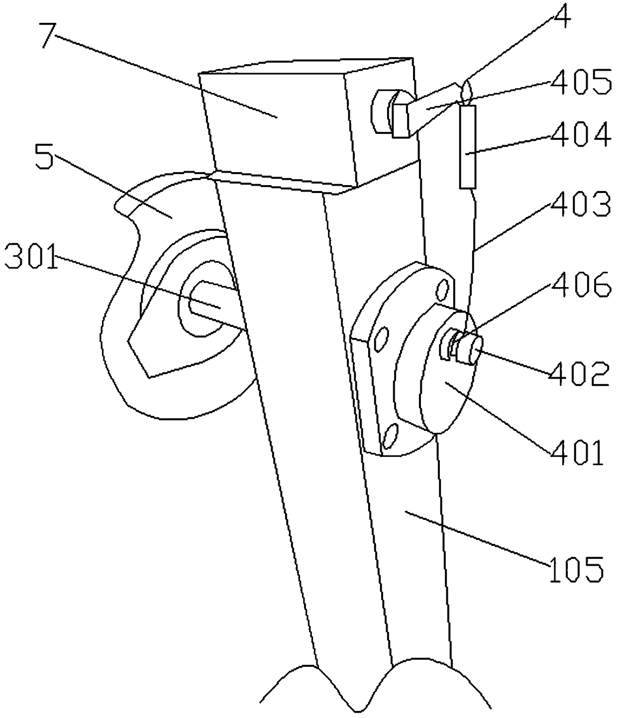
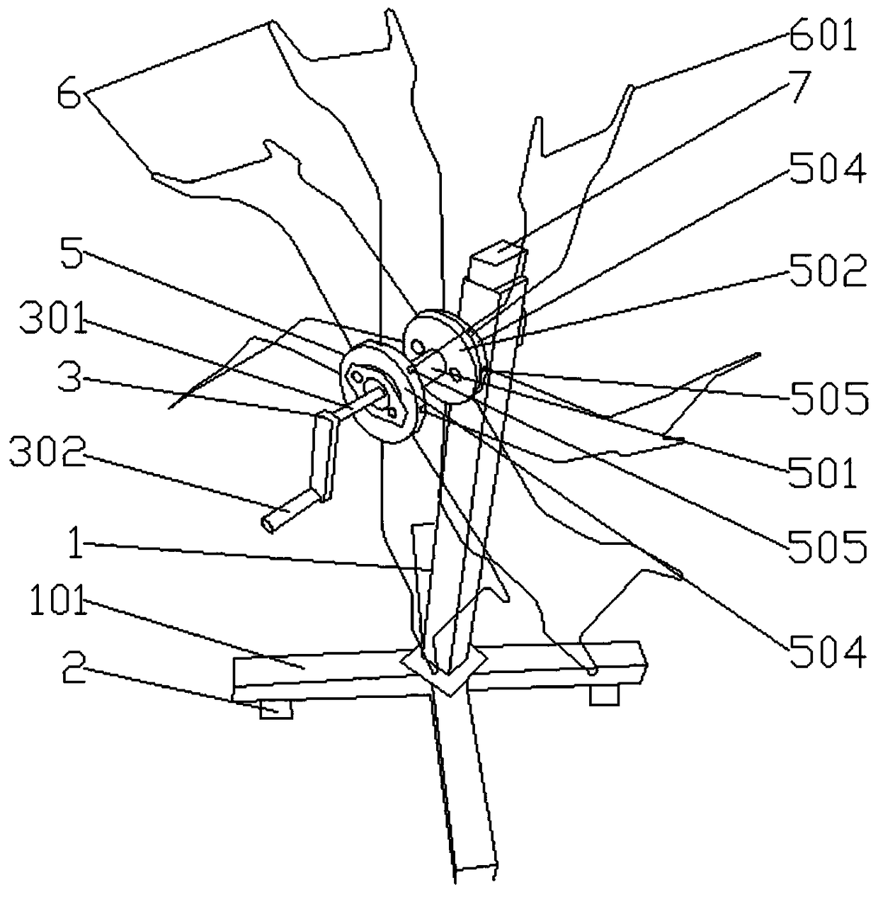
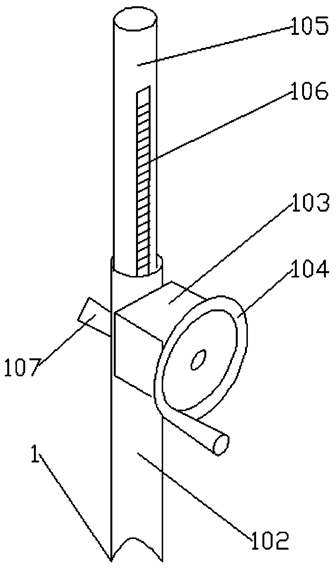
[0041] Such as figure 1 , figure 2 , image 3 , Figure 4 , Figure 5 , Figure 7 , Figure 8 , Figure 9 , Figure 10 , Figure 11 , Figure 12 , Figure 13 , Figure 14 with Figure 15 The height-adjustable spinning system shown includes a lifting frame 1, a number of supporting mechanisms 2 arranged at the bottom of the lifting frame, a rotating mechanism 3 arranged on the upper part of the lifting frame, a connecting piece 4 arranged on the rotating mechanism, and a The roulette assembly 5 on the rotating mechanism, the shelving assemblies 6 arranged on the roulette assembly, and the mechanical counting mechanism 7 arranged on the top of the lifting support, the connector is connected with the mechanical counting mechanism; the lifting support includes a base 101 and is arranged on ...


PUM


Abstract

The invention relates to the technical filed of textile machinery and equipment and particularly discloses a height-adjustable reeling system. The height-adjustable reeling system comprises a liftingbracket, supporting mechanisms, a rotating mechanism, a connecting piece, a wheel disc assembly, shed frame assemblies and a mechanical counting mechanism. The lifting bracket comprises a base and a supporting cylinder, a gear box is arranged on the supporting cylinder, a lifting rod is arranged in the supporting cylinder, and a rack is arranged on the lifting rod. The supporting mechanisms comprise transverse rods and sleeves, universal wheels are arranged at the bottoms of the transverse rods, supporting feet are connected to the transverse rods, adjusting discs are arranged on the supporting feet, and supporting rods are arranged in the sleeves. The connecting piece comprises a metal connecting rod and a spring, and a linkage plate is arranged at the end of the spring. The mechanical counting mechanism comprises a housing and a counting assembly. The counting assembly comprises a counting shaft, a carry shaft, counting discs and carry gears, end face supporting teeth are arranged onthe periphery of the single-digit counting disc of the counting assembly, and pawls are arranged at the end face supporting teeth. The height-adjustable reeling system has the characteristics of being good in flexibility, convenient to move and adjustable in height, and having the counting function.

Description

technical field [0001] The invention relates to the technical field of textile machinery and equipment, in particular to a height-adjustable spinning system. Background technique [0002] Textile machine is the full name of the tool that processes thread, silk, hemp and other raw materials into silk thread and then weaves cloth. Textile machine has a long history, which can be traced back to the Neolithic Age at the earliest. , Pedal looms, mechanical looms, and CNC looms. The function of the textile machine is more and more comprehensive, and the textile efficiency is also higher and higher. [0003] Before the enterprise produces textile products in the workshop according to the customer's requirements, it needs to make samples on the sample machine to check whether the products made by the sample machine meet the production requirements. If the small sample products meet the requirements, they will carry out mass production in the workshop. If the sample product does no...

Claims


Application Information

Patent Timeline
Patent Type & Authority Applications(China)
IPC IPC(8): B65H54/02B65H54/44B65H61/00G06M1/06G06M1/24
CPCG06M1/062G06M1/241B65H54/02B65H54/44B65H61/00B65H2701/31
Inventor 杨锋
Owner 德清县金丝源纺织品有限公司
Why Eureka
Try Eureka