On-line adjusting device used for oxygen-free copper wire tension and capable of adjusting tension conveniently
An oxygen-free copper wire and adjustment device technology, which is applied in the directions of transportation and packaging, delivery of filamentous materials, thin material processing, etc., can solve the problem of inconvenient and accurate tension adjustment, so as to avoid shaking, improve transmission strength, and improve stability Effect
- Summary
- Abstract
- Description
- Claims
- Application Information
AI Technical Summary
Problems solved by technology
Method used
Image
Examples
Embodiment 2
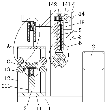
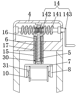
[0037] Embodiment 2: The difference with Embodiment 1 is that the inside of the transmission box 4 is provided with a transmission mechanism 14, the transmission mechanism 14 includes a worm screw 141, a worm wheel 142 and an L-shaped handle 143, and the worm screw 141 is movably connected to the inner wall of the transmission box 4 through a bearing. On the rear side, the worm 141 is located on the right side of the screw 15, the worm gear 142 is fixedly connected to the surface of the screw 15, the worm 141 is engaged with the worm gear 142, the L-shaped handle 143 is arranged on the front side of the transmission box 4, and the front end of the worm 141 runs through To the front side of the transmission box 4 and fixedly connected to the top of the back of the L-shaped handle 143, by setting the worm 141 and the worm wheel 142, the screw 15 can be driven to rotate, reducing the rotation speed of the screw 5 and improving the L-shaped handle. -143 to the transmission strength...
Embodiment 3
[0038] Embodiment 3: The difference from Embodiment 1 is that the surface of the screw sleeve 6 is covered with a fixed cylinder 15 located on the inner wall of the transmission box 4, the bottom end of the fixed cylinder 15 penetrates to the bottom of the transmission box 4, and the tops on both sides of the screw sleeve 6 All are fixedly connected with slide block 16, both sides of fixed tube 15 inner walls are provided with chute 17, slide block 16 is slidably connected in the inside of chute 17, by arranging slide block 16 and chute 17, screw sleeve 6 can be The position limit prevents the screw sleeve 6 from turning when it moves up and down, and improves the stability of the screw sleeve 6 when it moves.
Embodiment 4
[0039] Embodiment 4: The difference from Embodiment 1 is that a pressing mechanism 18 is provided on the left side of the transmission box 4, and the pressing mechanism 18 includes a fixing plate 3 181, a connecting cylinder 182, a screw 2 183, an L-shaped handle 2 184, and a square sleeve 185, backing plate 3 186, backing plate 4 187 and pressing shaft 188, fixed plate 3 181 is fixedly connected to the bottom on the left side of transmission box 4, connecting cylinder 182 is fixedly connected to the left side of fixed plate 3 181, and screw rod 2 183 is set On the top of the connecting cylinder 182, the L-shaped handle 184 is fixedly connected to the top of the screw 183, the bottom of the screw 183 penetrates to the inside of the connecting cylinder 182, and the square sleeve 185 is threaded on the bottom of the surface of the screw 183. The sleeve 185 is slidingly connected to the inside of the connecting cylinder 182, the third backing plate 186 is fixedly connected to the ...
PUM
 Abstract
Description
Claims
Application Information
 - R&D
- Intellectual Property
- Life Sciences
- Materials
- Tech Scout
- Unparalleled Data Quality
- Higher Quality Content
- 60% Fewer Hallucinations
Browse by: Latest US Patents, China's latest patents, Technical Efficacy Thesaurus, Application Domain, Technology Topic, Popular Technical Reports.
© 2025 PatSnap. All rights reserved.Legal|Privacy policy|Modern Slavery Act Transparency Statement|Sitemap|About US| Contact US: help@patsnap.com


