
Warp beam dyeing machine reversing device

A technology of a commutator device and a dyeing machine is applied in the field of dyeing machinery, which can solve the problems of increasing power consumption, increasing pump power, and increasing costs, and achieves the effects of saving energy consumption, reducing pump power, and reducing operating costs.

Pending Publication Date: 2019-01-04
无锡承创机械设备有限公司
View PDF0 Cites 0 Cited by
  • Summary
  • Abstract
  • Description
  • Claims
  • Application Information

AI Technical Summary

Problems solved by technology

This technical method cannot completely solve the head-to-tail difference phenomenon, but can only improve it. Increasing the pump power will increase power consumption, resulting in energy waste and cost increase.

Method used


Image

  • Warp beam dyeing machine reversing device
  • Warp beam dyeing machine reversing device

Examples


Embodiment 1

Embodiment 2

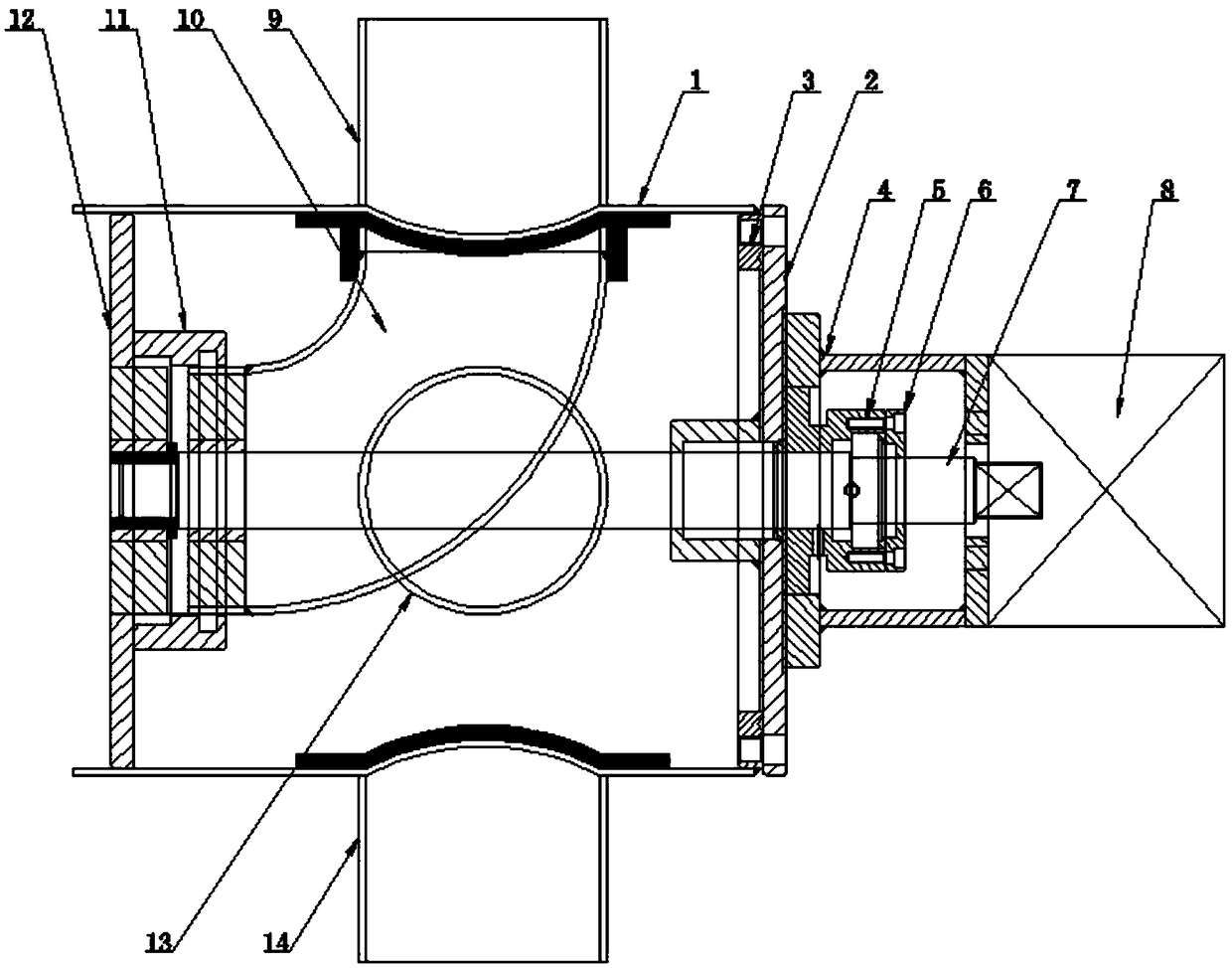
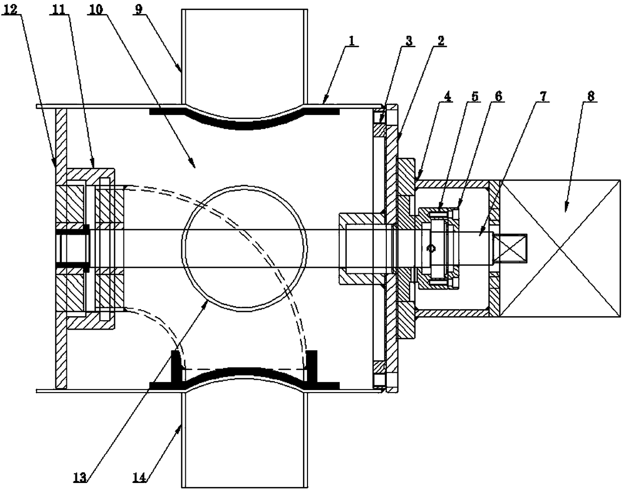
[0018] Embodiment 2: as figure 2 As shown, a reversing device for a warp beam dyeing machine of the present invention includes a reversing device cylinder 1, and the reversing device cylinder 1 includes a flow regulating device cover plate 2, an actuator base 4, a flow regulating sealing device 5, Flow regulation and reversing shaft 7, actuator 8, pump injection port 9, flow regulation elbow 10, flow regulation fixed flange 12, flow regulation suction port 13 and pump suction port 14, the flow regulation device cover plate 2 Set at one end of the reversing device cylinder 1; the actuator base 4 is set on the cover plate 2 of the flow regulating device; the flow regulating sealing device 5 is set inside the actuator base 4; the flow regulating and reversing shaft 7 is horizontally Through the cylinder body 1 of the reversing device; the actuator 8 is arranged on the actuator base 4; the pump injection port 9 is arranged at the upper opening of the cylinder body 1 of the revers...


PUM


Abstract

The invention provides a warp beam dyeing machine reversing device. The device comprises a reversing device cylinder. The reversing device cylinder comprises a flow regulating device cover plate, an actuator pedestal, a flow regulating sealing device, a flow regulating reversing shaft, an actuator, a pump injection port, a flow regulating elbow, a flow regulating fixing flange, a flow regulating water suction port and a pump water suction port. The flow regulating device cover plate is arranged on one end of the reversing device cylinder. The actuator pedestal is arranged on the flow regulating device cover plate. The flow regulating sealing device is arranged in the actuator pedestal. The flow regulating reversing shaft transversely passes through the reversing device cylinder. The actuator is arranged on the actuator pedestal. The pump injection port is arranged at an opening above the reversing device cylinder. One end of the flow regulating elbow is connected to the pump injectionport or the pump water suction port. The other end of the flow regulating elbow is connected into a warp beam dyeing machine. The flow regulating fixing flange is arranged on the other end of the reversing device cylinder. The flow regulating water suction port is arranged at the center position in the reversing device cylinder. The pump water suction port is arranged at an opening below the reversing device cylinder. The device has low energy consumption and cost is low.

Description

technical field [0001] The invention relates to the technical field of dyeing machinery, in particular to a reversing device for a warp beam dyeing machine. Background technique [0002] Warp beam dyeing machine is a new equipment that has emerged in recent years. It is an essential dyeing machine for printing and dyeing factories. Due to its mechanical composition characteristics, it is mainly suitable for dyeing filament and light fabrics; During the processing, the superiority of dyeing is shown; the working principle of the warp beam dyeing machine is to wrap the fabric to be dyed on the dyeing cylinder covered with liquid holes on the surface, and the dyeing liquid is introduced into the dyeing cylinder under high pressure. into the cylinder cavity, and penetrate into the fabric through the aforesaid liquid hole, repeat this way and complete the dyeing of the fabric after the required time, then remove the dyeing cylinder from the machine, and unload the previous wrappi...

Claims


Application Information

Patent Timeline
IPC IPC(8): D06B23/20D06B1/08
CPCD06B1/08D06B23/20
Inventor 李燕杰
Owner 无锡承创机械设备有限公司
Learn More