
Fluorescence source with reinforced spectral selectivity

A selective, spectroscopic technique used in the field of fluorescent sources

Inactive Publication Date: 2006-02-22
SHANGHAI INST OF OPTICS & FINE MECHANICS CHINESE ACAD OF SCI
View PDF0 Cites 0 Cited by
  • Summary
  • Abstract
  • Description
  • Claims
  • Application Information

AI Technical Summary

Problems solved by technology

Considering the loss, spectral width and pump power requirements, it is not ideal to use coated reflectors and fiber reflectors as reflective devices in the monitoring light source used in the production process of fiber distributed feedback single longitudinal mode lasers.

Method used


Image

  • Fluorescence source with reinforced spectral selectivity

Examples


Embodiment Construction

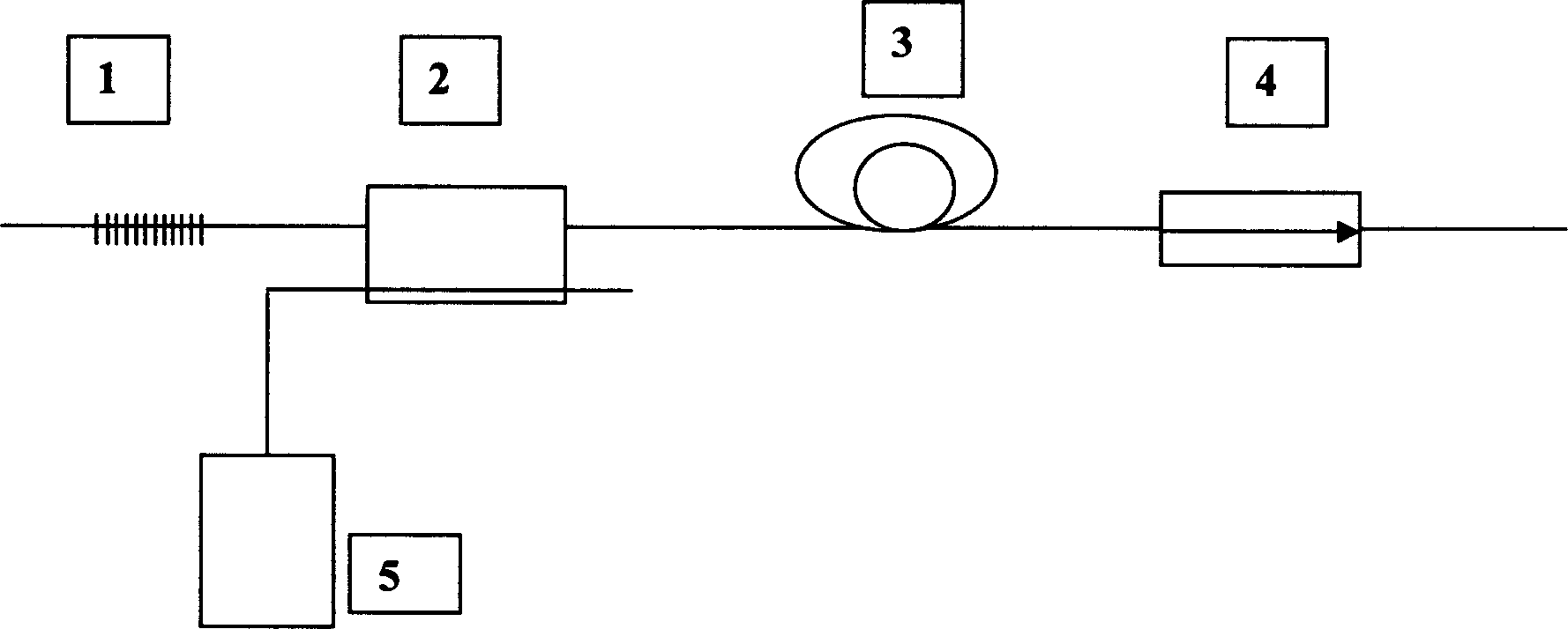
[0013] see first figure 1 , figure 1 It is the optical path diagram of the structure of the fluorescence source embodiment of spectral selectivity enhancement of the present invention, as can be seen from the figure, the structure of the fluorescence source of spectral selectivity enhancement of the present invention is: one end of a fiber grating 1 and a wavelength division multiplexer 2 The first input end is connected, the output end of this wavelength division multiplexer 2 is connected to a doped fiber 3, the other end of this doped fiber 3 is output through a fiber isolator 4, and the output end of a semiconductor laser 5 is connected to the described At the second input end of the wavelength division multiplexer 2, the reflectivity of the fiber grating 1 is 30 decibels, the reflection spectrum is approximately square, and the reflection bandwidth is 2nm.

[0014] The fiber grating 1 is connected in series by more than one fiber grating.

[0015] The principle of the w...


PUM


Abstract

This invention relates to one fluorescence power with spectrum choice strengthening, which comprises the following structure: one end of fiber grating is connected to first input end of wave splitter multiplexer and with its output end connected to one mixing fiber; the other end of the fiber is outputted though one fiber isolator; the output end of one semiconductor is connected to the second input end of the multiplexer; the said fiber grating reflection rate is as 30 decibel and with reflection spectrum nears to squareness and reflection band width as 2nm.

Description

technical field [0001] The invention relates to a fluorescent source, in particular to a fluorescent source with enhanced spectral selectivity. The fluorescence source can be used for spectrum analysis of the fiber grating and the fiber distribution feedback laser, and can be used as a monitoring light source in the process of manufacturing the fiber grating and the fiber distribution feedback laser. It can also be used in the field of spectral analysis and sensors of other fiber optic components. Background technique [0002] The fiber distributed feedback single longitudinal mode laser can be used as the main oscillator in the front-end system of the inertial confinement nuclear fusion laser driver (see literature 1: Howard, T.powell'long-term wavelength and gain stability demonstrated by NIF master oscillator components'laser science & technology , march 2000.), can be used in fiber optic sensors (see literature 2: D.J.Hill, P.J.Nash, D.A.Jackson and etc.'A fiber laserhy...

Claims


Application Information

Patent Timeline
IPC IPC(8): G01J3/10G01N21/17
Inventor 陈柏梁丽萍陈嘉琳
Owner SHANGHAI INST OF OPTICS & FINE MECHANICS CHINESE ACAD OF SCI
Learn More