
Gain medium of Raman amplifier

A Raman amplifier, gain medium technology, applied in instruments, optics, nonlinear optics, etc., can solve the problems of difficult FRA, reduced size, low gain coefficient, etc., achieve lattice structure optimization, low pumping optical power, high gain effect

Inactive Publication Date: 2009-05-27
UNIV OF ELECTRONICS SCI & TECH OF CHINA
View PDF4 Cites 0 Cited by
  • Summary
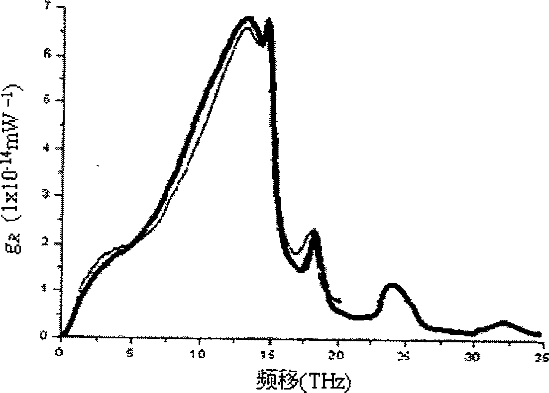
  • Abstract
  • Description
  • Claims
  • Application Information

AI Technical Summary

Problems solved by technology

[0007] In fact, the most important factor that determines the performance of FRA is the Raman gain coefficient of the optical fiber. Since the Raman gain coefficients of traditional optical fibers are relatively low, the length of the optical fiber of the general FRA is more than ten kilometers to tens of kilometers. It is difficult to reduce the size of the vertical FRA, which limits the use of discrete FRA. In fact, almost all commercial FRAs are Raman pumping modules that realize distributed amplification. However, with the capacity, bandwidth and distance of the DWDW system Further improvement, the discrete FRA that realizes the transmitter back-end power boost amplification and the receiver front-end power pre-amplification will definitely make a difference
At the same time, because the Raman gain coefficient is relatively low, it is necessary to use a high-power semiconductor laser or use a pumping optical combiner to combine multiple pumping sources to increase the power, which also increases the complexity of the system.
In addition, the Raman gain coefficient spectrum of various types of traditional optical fibers is very uneven, so to maintain a certain gain flatness in a wide gain band of FRA requires more pumping light sources at the same time, which increases the manufacturing cost , which also increases the complexity of the design method
[0008] Based on the above analysis, it can be seen that the FRA using traditional optical fiber as the gain medium has been developed relatively maturely, and some commercial products have appeared, but there are problems in the design of multiple pumping sources, the difficulty of flattening the broadband gain spectrum, and the problems of pumping sources. The problem of low conversion efficiency
This limits the large-scale promotion and utilization of FRA, especially discrete FRA
Although increasing the power of pumping and increasing the number of pumps can alleviate the above problems to a certain extent, this will inevitably greatly increase the production cost of FRA and the complexity of design and manufacture.

Method used


Image

  • Gain medium of Raman amplifier
  • Gain medium of Raman amplifier
  • Gain medium of Raman amplifier

Examples


Embodiment 1

[0035] Referring to the photonic crystal fiber structure of solid light guide, it is composed of quartz and air holes in the cladding, which can be regarded as the quartz in the center surrounded by air holes. In view of this, the present invention calls such a structure a light guide unit, the central solid part is called a central optical waveguide area (core), and the peripheral air hole and its surrounding areas are called an external field area. like Figure 5 As shown, the central optical waveguide area is inside the middle ring, and the outer area with air holes is the outer field area.

[0036] See Figure 4. This embodiment includes a first light guide unit and a second light guide unit, and the second light guide unit is distributed in the outer field area of ​​the first light guide unit and is surrounded by air holes of the first light guide unit. The structures of the first and second light guide units are arranged in the manner of photonic crystal fiber, that is,...


PUM


Abstract

A gain media of Raman amplifier is prepared for distributing the second light guide unit in external field region of the first light guide unit and using air-hole of the first light guide unit to surround the second light guide unit.

Description

technical field [0001] The invention relates to optical fiber communication technology. Background technique [0002] Fiber Raman amplifier (fiber Raman amplifier, FRA) has been recognized as a large-capacity dense wavelength division multiplexing (DWDM), long-distance One of the key technologies of (long-haul, LH) and ultra-long-haul (ULH) optical fiber transmission systems. [0003] FRA works according to the principle of stimulated Raman scattering (stimulited Raman scattering, SRS). Generally speaking, the high-energy laser transmitted in the nonlinear optical medium will be scattered, and a small part of the incident power will be transferred to another frequency. The amount of frequency change is determined by the properties of the medium, and this process is called spontaneous Raman scattering. If a weak signal light and a higher-frequency strong pump light are transmitted in the nonlinear optical medium at the same time, and the frequency of the signal light is wit...

Claims


Application Information

Patent Timeline
Patent Type & Authority Patents(China)
IPC IPC(8): G02F1/39G02B6/02
Inventor 姜海明王文丹谢康王亚非
Owner UNIV OF ELECTRONICS SCI & TECH OF CHINA
Learn More