
Construction method of large cross-section embedded rigid column feet

A construction method and embedded technology, applied in the directions of columns, pillars, piers, etc., can solve the problem of small installation space for column feet, and achieve the effect of reducing construction difficulty, improving integrity, and saving cost of measures.

Active Publication Date: 2020-08-04
HANGZHOU JIANGRUN TECH LIMITED
View PDF5 Cites 0 Cited by
  • Summary
  • Abstract
  • Description
  • Claims
  • Application Information

AI Technical Summary

Problems solved by technology

Although this construction method solves the problem of small installation space of the column foot and improves the construction efficiency to a certain extent, there are still some improvements in the shear resistance and integrity of the column foot and the improvement of the positioning accuracy of the components.
[0004] In summary, although the existing construction methods have achieved good construction results under suitable working conditions, there are still deficiencies in the improvement of the shear resistance and integrity of column feet, and the improvement of component installation and positioning accuracy.

Method used


Image

  • Construction method of large cross-section embedded rigid column feet
  • Construction method of large cross-section embedded rigid column feet
  • Construction method of large cross-section embedded rigid column feet

Examples


Embodiment Construction

[0038] The present invention will be further described below in conjunction with embodiments. The description of the following embodiments is only used to help understand the present invention. It should be pointed out that for those of ordinary skill in the art, without departing from the principle of the present invention, several improvements and modifications can be made to the present invention, and these improvements and modifications also fall within the protection scope of the claims of the present invention.

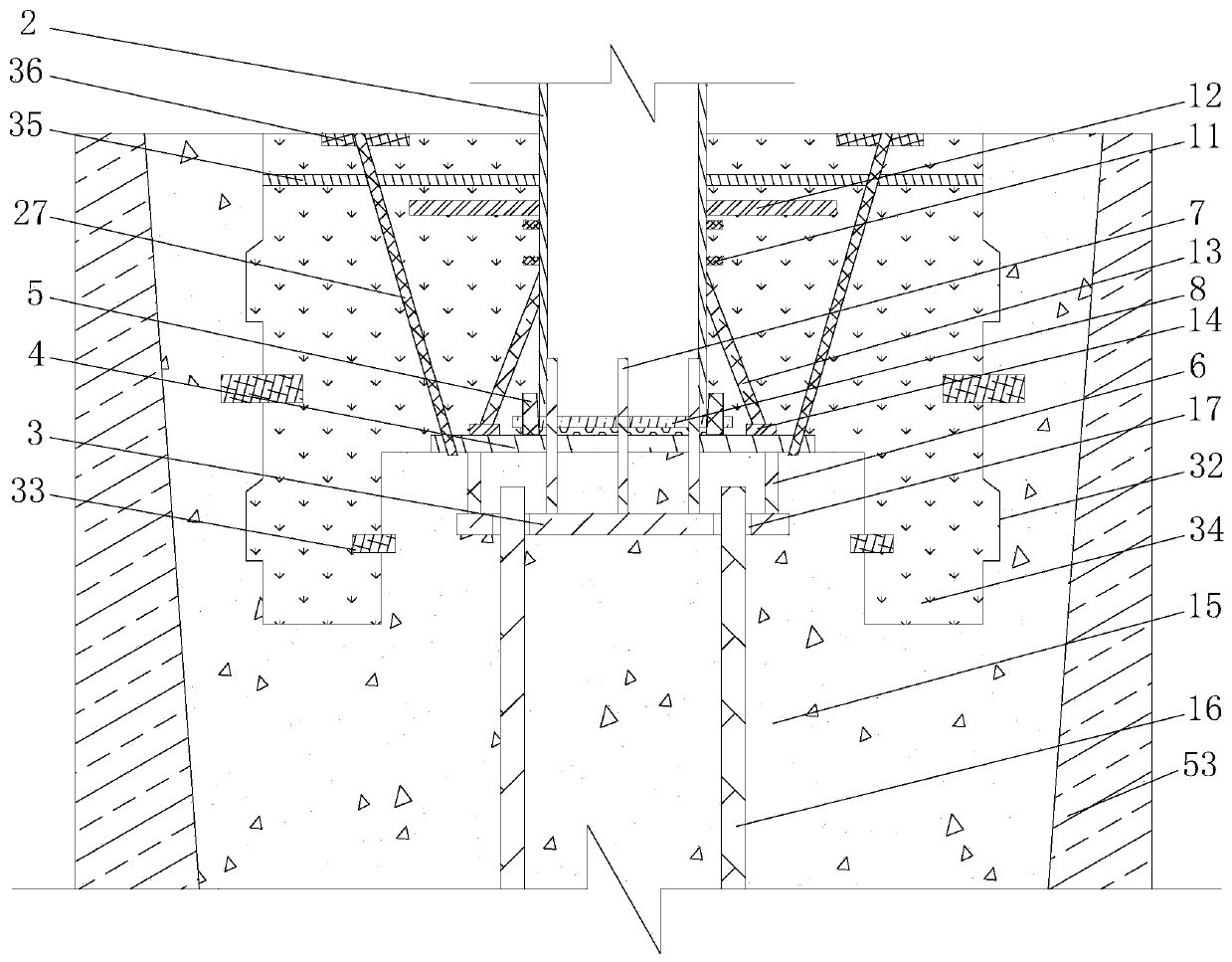
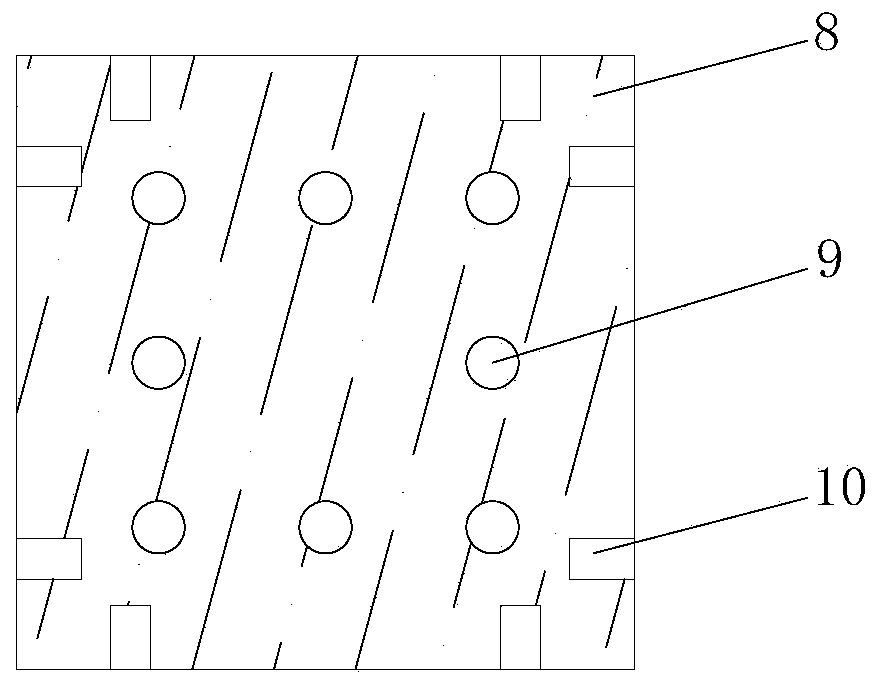
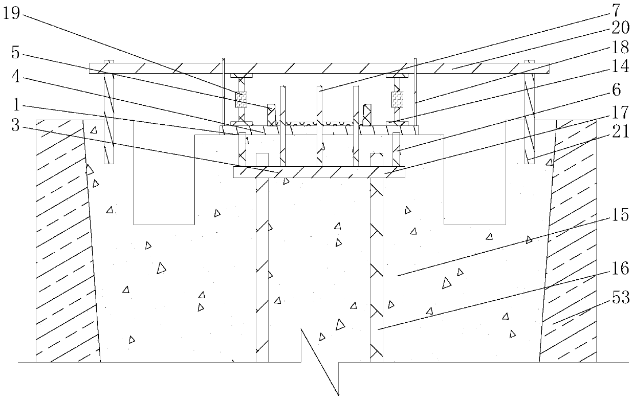
[0039] Reference Figure 1~Figure 10 As shown, the large cross-section embedded rigid column foot has a positioning connector 1 preset inside the first column foot concrete 15; a ground anchor connection connected to the positioning connector 1 is provided at the bottom of the steel column connection section 2 Plate 8, reinforced connecting ribs 11, pressure dispersing plates 12 and diagonal support ribs 13 are arranged on the outside; when the positioning connect...


PUM


Abstract

The invention relates to a construction method for a large-section embedded stiff column base. The construction method comprises the following steps: 1) manufacturing a positioning connecting body anda steel column connecting section; 2) excavating a basic soil body; 3) carrying out concrete pouring construction for a first column base; 4) setting a prestress tie bar; 5) hoisting and positioningthe steel column connecting section; 6) carrying out concrete pouring of a second column base; 7) tensioning the prestress tie bar. According to the construction method, the positioning connecting body comprising a positioning bottom plate and a bearing top plate is arranged, and the positioning connecting body and a basic reinforcement cage are connected, so that the connecting strength and integrity of the column base and a lower structure can be enhanced effectively. An inclined supporting rib is arranged between the steel column connecting body and the basic reinforcement cage and a reinforcing connecting rib and a pressure dispersing plate are arranged on the outer surface, so that the connecting strength between the steel column connecting section and concrete of the second column base can be enhanced effectively, and the peak stress of the structure is dispersed.

Description

Technical field [0001] The invention relates to a construction method for installing rigid column feet, in particular to a construction method for large-section buried rigid column feet with good structural integrity, high on-site construction efficiency, and reliable positioning and assembly quality, and belongs to the field of house construction , It is suitable for the installation of rigid column foot. Background technique [0002] With the development of my country's economy, the scale of construction projects continues to expand, and there are more and more super high-rise buildings in the city. The rigid steel column foot is an important part of the connection between the upper main structure of the super high-rise building and the foundation. According to the structure, it can be divided into three types: exposed type, embedded type and outsourcing type. In the process of embedded installation and construction of engineering rigid steel columns in super high-rise buildin...

Claims


Application Information

Patent Timeline
Patent Type & Authority Patents(China)
IPC IPC(8): E04C3/32
CPCE04C3/32
Inventor 王新泉
Owner HANGZHOU JIANGRUN TECH LIMITED
Learn More