
Welding and roasting device for diode

A technology of baking device and diode, applied in drying, drying machine, drying gas arrangement and other directions, can solve the problem of easy bending and deformation of diode pins, and achieve the advantages of enhancing drying quality, avoiding bending and ensuring processing quality. Effect

Active Publication Date: 2019-01-04
泸州龙芯微科技有限公司
View PDF5 Cites 0 Cited by
  • Summary
  • Abstract
  • Description
  • Claims
  • Application Information

AI Technical Summary

Problems solved by technology

[0004] The present invention intends to provide a diode welding and baking device to solve the problem that the diode pins are easily bent and deformed due to the existing use of a disk body to sieve the diode to dry the diode

Method used


Image

  • Welding and roasting device for diode
  • Welding and roasting device for diode
  • Welding and roasting device for diode

Examples


Embodiment Construction

[0021] The present invention will be described in further detail below by means of specific embodiments:

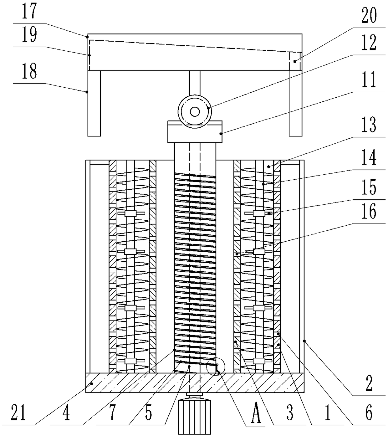
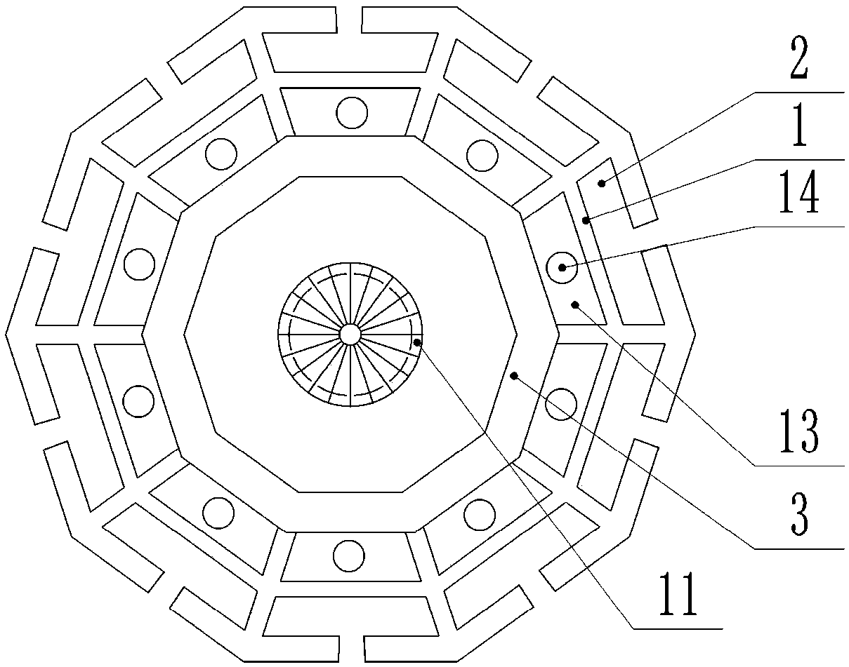
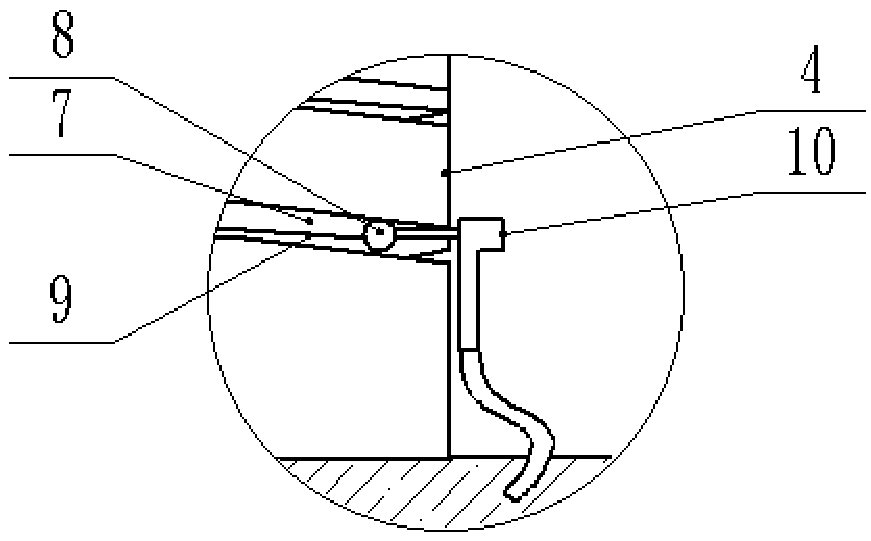
[0022] The reference signs in the drawings of the description include: drying cylinder 1, drying tank 2, spacer 3, shaft tube 4, rotating shaft 5, drying hole 6, chute 7, slider 8, pull cord 9, hot air head 10. Rotary gear 11, winding gear 12, cavity 13, screw shaft 14, fan wheel 15, ventilation hole 16, tank body 17, discharge pipe 18, cylindrical cam 19, discharge channel 20, chassis 21.

[0023] Example figure 1 Shown: including drying cylinder 1, drying mechanism, lifting mechanism and feeding mechanism.

[0024] The drying cylinder 1 is used for baking the diode. combine figure 2 As shown, the outer wall of the drying cylinder 1 is provided with a plurality of drying grooves 2 for placing diodes, and the drying grooves 2 extend along the axial direction of the drying cylinder 1, and a plurality of drying grooves 2 surround the drying cylinder The axes of the cyl...


PUM


Abstract

The invention relates to the field of welding and roasting devices for diodes, and discloses a welding and roasting device for a diode. The device comprises a roasting barrel, wherein a plurality of roasting grooves are formed in the outer wall of the roasting barrel, and the roasting grooves axially extend along the roasting barrel; the plurality of roasting grooves are sequentially annularly distributed around an axis of the roasting barrel; a plurality of roasting holes are formed in the roasting barrel; and a roasting mechanism is arranged in the roasting barrel. The device solves the problem that a pin of the diode is easily bent and deformed when the diode is screened through a plate body during roasting in the prior art can be solved.

Description

technical field [0001] The invention relates to the field of diode welding and drying devices, in particular to a diode welding and drying device. Background technique [0002] Diodes are commonly used electronic devices in circuit structures. Diodes have two pins. During production and processing, the two pins are connected to the housing of the diode through subsequent welding operations. In order to ensure the welding effect of the pins, it is necessary to Bake the soldered diodes to solidify the solder on the soldered parts and ensure the fixation of the pins. [0003] Due to the small size of the diodes, it is difficult to bake them alone. Therefore, the existing method of baking diodes is to use a sieve plate to sieve piles of diodes, and at the same time, a heat source is introduced into the plate to make the diodes It is baked on the plate. This baking method has high processing efficiency. However, since the pins of the diode are usually made of copper-plated iron ...

Claims


Application Information

Patent Timeline
Patent Type & Authority Applications(China)
IPC IPC(8): F26B17/12F26B21/00F26B25/00
CPCF26B17/12F26B21/004F26B25/002
Inventor 黄晓波
Owner 泸州龙芯微科技有限公司
Learn More