Efficient and accurate calibration method for laser interferometer optical path based on PSD

A technology of a laser interferometer and a calibration method, applied in the optical field, can solve the problems of low accuracy and low efficiency of the adjustment process, and achieve the effects of improving efficiency and precision, improving the efficiency and precision of calibration, and improving practicability.

Active Publication Date: 2019-01-04
CHENGDU AIRCRAFT INDUSTRY GROUP
View PDF7 Cites 25 Cited by
  • Summary
  • Abstract
  • Description
  • Claims
  • Application Information

AI Technical Summary

Problems solved by technology

[0005] At present, the problems of this measurement method are mainly manifested in: (1) The direction of the space measurement line segment established according to the machine tool geometric error identification method is diverse. For example, the measurement line segment of a single translation axis is along the X, Y, and Z directions of the machine tool coordinate system. , and the XZ, XY, XYZ multi-axis linkage measurement line segment forms a certain inclination angle with each coordinate axis, and according to the measurement principle of the laser interferometer, it must be ensured that the measurement light returned by the moving corner mirror is consistent with the reference corner mirror. The reference reflected light interferes at the receiving head of the laser interferometer, which requires adjusting the position of the laser interferometer to calibrate the optical path to ensure that the measurement light can return to the receiving head; (2) The current way to calibrate the optical path is only for engineers to use a tripod for laser interference The fine-tuning of the instrument position relies too much on engineering experience, and the adjustment process has low efficiency and low accuracy

Method used


Image

  • Efficient and accurate calibration method for laser interferometer optical path based on PSD
  • Efficient and accurate calibration method for laser interferometer optical path based on PSD
  • Efficient and accurate calibration method for laser interferometer optical path based on PSD

Examples


Embodiment 1

[0047] A PSD-based efficient and accurate calibration method for laser interferometer optical path mainly includes the following steps:

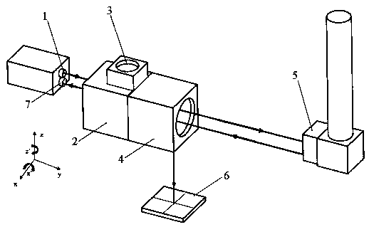
[0048] Step S101: Establish a system optical path, such as figure 1 As shown, the emission light A emitted by the laser interferometer emission head 1 is divided into reflected light and transmitted light by the interference beam splitter 2, and the reflected light passes through the reference pyramid reflector 3 to form a reference reflected light B and returns to the interference beam splitter 2 and then returns to the laser interference The receiving head 7 of the instrument; the transmitted light forms the moving reflected light C through the moving corner mirror 5 and returns to the mirror to be divided into the calibration light D and the measurement light E, and the calibration light D is projected on the PSD two-dimensional photosensitive position sensor 6 to obtain two Dimensional coordinates, the direction of the emission light A ...

Embodiment 2

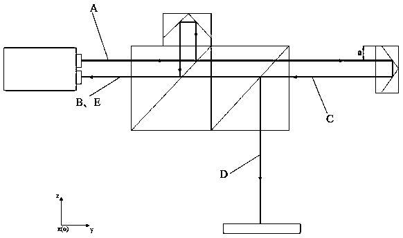
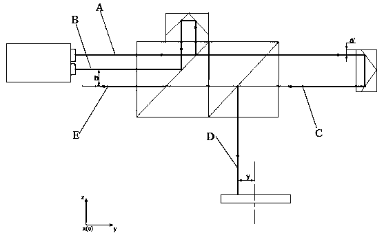
[0053] This embodiment is optimized on the basis of embodiment 1, such as Figure 2-4 As shown, in the step S101, the equation of the standard light offset and the measurement light E offset is established; , then the measurement light E offset is equal to y, where y is the y coordinate value of the calibration light D spot on the PSD two-dimensional photosensitive position sensor 6; as Figure 5-7 As shown, when the moving cube mirror moves left and right along the X axis in the XY plane or yaws and rotates around the Z axis, the offset of the measurement light E is equal to x, where x is the calibration light D spot in the PSD two-dimensional The x-coordinate value on the photosensitive position sensor 6.

[0054] The present invention obtains the offset of the calibration light D spot in the PSD relative to the zero point of the PSD coordinate system through the data acquisition card, that is, the current coordinate value (x, y). The data acquisition card and post-process...

Embodiment 3

[0061] This embodiment is optimized on the basis of embodiment 2, such as Figure 8 As shown, the threshold value is 10mm, and step S104 is also included: controlling the machine tool spindle to move from the starting point to the end position along the measurement line segment, if the measurement light E is always projected on the center of the laser interferometer receiving head 7 and interferes with the reference reflected light B , the optical path calibration is completed. The main shaft of the machine tool moves along the measurement line segment of the error identification method, ensuring that the moving corner mirror 5 is perpendicular to the measurement line segment, so that the moving reflected light C is parallel to the measurement line segment.

[0062] The present invention realizes the automatic calibration of the optical path of the laser interferometer through the coordinates measured in the PSD two-dimensional photosensitive position sensor 6. The present inv...


PUM


Abstract

The invention discloses an efficient and accurate calibration method for a laser interferometer optical path based on a PSD. Firstly the system optical path is established, then the laser interferometer optical path is roughly adjusted, and finally the coordinate values of each calibration point is obtained according to the PSD two-dimensional photosensitive position sensor and the offset of the measurement light relative to the reference reflected light is calculated and the laser interferometer optical path is precisely adjusted according to the offset. Automatic calibration of the laser interferometer optical path is realized through the coordinates measured in the PSD two-dimensional photosensitive position sensor, and the offset of the calibration beams is obtained by using the PSD two-dimensional photosensitive position sensor so as to indirectly obtain the offset of the measurement light, realize automatic adjustment of the optical path, realize the high-precision optical path calibration, improve the calibration efficiency and accuracy and have good practicability.

Description

technical field [0001] The invention belongs to the field of optical technology, and in particular relates to a high-efficiency and precise calibrating method for an optical path of a laser interferometer based on PSD. Background technique [0002] Multi-axis CNC machine tools are widely used in the processing of parts and components in the fields of aerospace and automobile manufacturing, and often require high geometric accuracy. The geometric accuracy is mainly divided into two aspects: (1) Multi-axis CNC machine tools (2) During the use of the multi-axis CNC machine tool, its geometric accuracy will decrease, and the geometric accuracy of the current machine tool. [0003] In order to stabilize the geometric accuracy of the machine tool at a high level, it is necessary to regularly detect the geometric accuracy of the machine tool and compensate for the resulting geometric errors. The geometric error of the machine tool can be effectively obtained by using the geometric...

Claims


Application Information

Patent Timeline
Patent Type & Authority Applications(China)
IPC IPC(8): G01B9/02
CPCG01B9/02072
Inventor 冯超钰李杰夏文涵陈云宋智勇李卫东
Owner CHENGDU AIRCRAFT INDUSTRY GROUP
Why Eureka
Try Eureka