Train crack detection device

A crack detection and train technology, applied in the direction of material magnetic variables, etc., can solve the problems of low detection efficiency, high detection environment requirements, high labor intensity of hollow shaft detection, etc., and achieve the effect of high detection efficiency

Inactive Publication Date: 2019-01-04
西安安源智造机电设备有限公司
View PDF5 Cites 0 Cited by
  • Summary
  • Abstract
  • Description
  • Claims
  • Application Information

AI Technical Summary

Problems solved by technology

[0005] Based on the above technical problems, the present invention provides a crack detection device for trains, thereby solving the technical problems of high labor intensity, low detection efficiency and high requirements for the detection environment in the past for the detection of hollow shafts of trains

Method used


Image

  • Train crack detection device
  • Train crack detection device

Examples


Embodiment 1

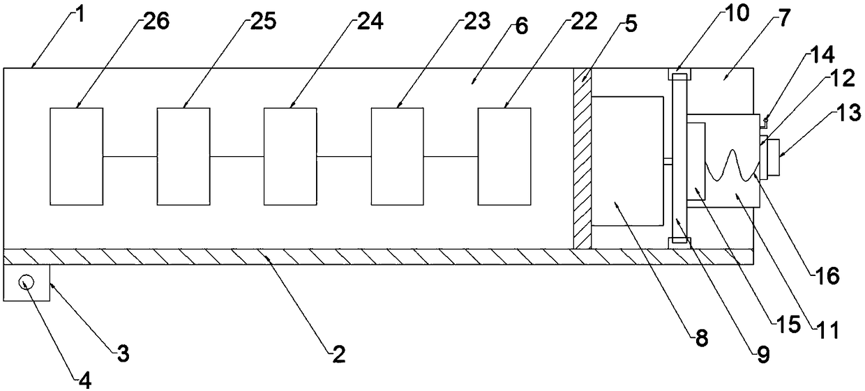
[0019] Such as Figure 1-2 As shown, a crack detection device for a train comprises a fixed barrel 1, the bottom of the fixed barrel 1 is provided with a rack 2 along the length direction of the fixed barrel 1, and a gear 3 meshing with the rack 2 is arranged below the rack 2. 3 connected with the first motor 4.

[0020] The fixed barrel 1 is provided with a baffle 5, and the baffle 5 divides the fixed barrel 1 into a first chamber 6 and a second chamber 7; the second chamber 7 is provided with a second motor 8, and the second motor 8 Fixed on the baffle plate 5, the output shaft of the second motor 8 is connected with a rotating disk 9; the fixed barrel 1 is provided with a rotating groove 10 along the circumferential direction of the fixed barrel 1, and the rotating disk 9 is located in the rotating groove 10 And can rotate along the rotating groove 10, the rotating barrel 11 is fixed on the rotating disk 9, the end of the rotating barrel 11 runs through the fixed barrel 1 ...

Embodiment 2

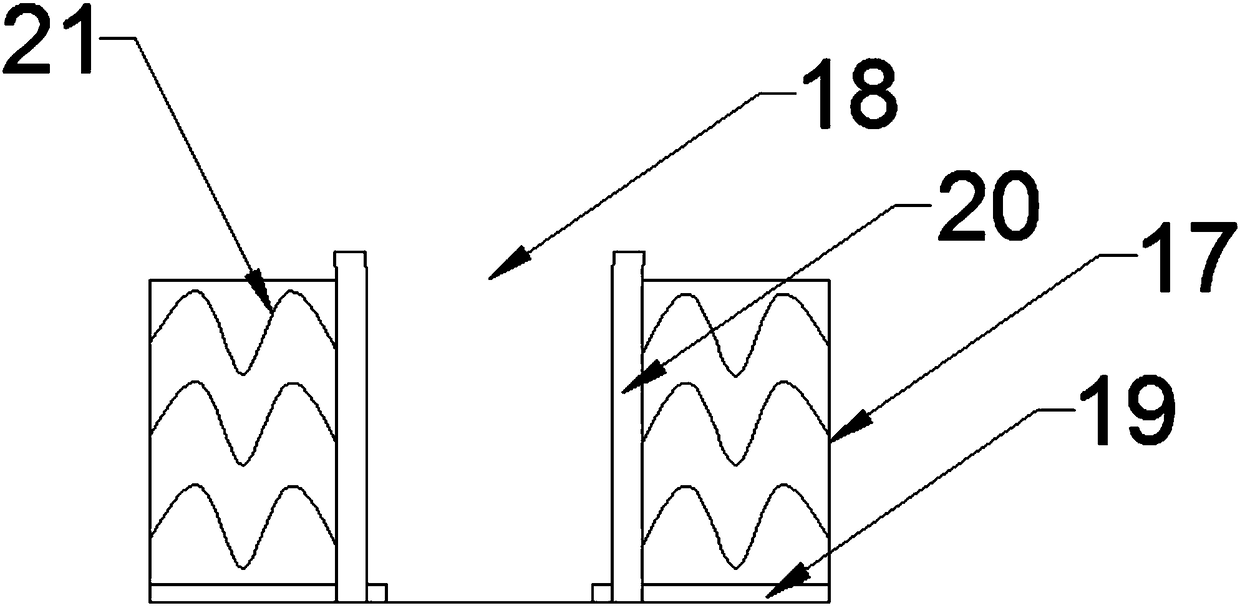
[0023] On the basis of Example 1, such as figure 2 As shown, the fixed assembly includes a hollow cylinder 17, the hollow cylinder 17 is fixed to the fixed port 12 and communicates with the rotating bucket 11, the top of the hollow cylinder 17 is provided with a probe inlet 18, and the bottom of the hollow cylinder 17 is uniformly arranged along the radial direction of the hollow cylinder 17. There are several moving grooves 19, and vertical baffles 20 are arranged in the moving grooves 19, and the top of the vertical baffles 20 passes through the probe inlet 18 and is inclined outside; a spring 21;

[0024] When using this embodiment, the fixed part of the probe 13 is placed between the vertical baffles 20, and the spring 21 gives an elastic force to the vertical baffle 20, thereby fixing the probe 13 stably; the top of the vertical baffle 20 passes through the probe 13 The entrance is inclined outwards, so that the size of the entrance of the probe 13 can be increased to e...

Embodiment 3

[0026] On the basis of embodiment 1-2, such as Figure 1-2 As shown, the probe 13 is connected with a signal amplifier 22, and the signal amplifier 22 is connected with a peak hold circuit 23, and the peak hold circuit 23 is connected with an A / D converter 24, and the A / D converter 24 is connected with a stand-alone controller 25, and the stand-alone Controller 25 is connected with alarm 26; Between described probe 13, signal amplifier 22, peak hold circuit 23, A / D converter 24, stand-alone controller 25 and alarm 26, connect by signal line, described signal amplifier 22 , peak hold circuit 23, A / D converter 24, stand-alone controller 25 and alarm 26 are all located in the first chamber 6;

[0027] When this embodiment is used, the front device 15 generates an eddy current on the inner surface of the hollow shaft through the probe 13, and the eddy current simultaneously generates a magnetic field opposite to the original magnetic field, and offsets part of the original magneti...


PUM


Abstract

The invention belongs to the technical field of detection of train cracks and relates to a train crack detection device. The train crack detection device comprises a fixed barrel which is provided with a rack, a gear meshed with the rack is arranged below the rack and connected with a first motor, and a baffle is arranged in the fixed barrel and divides the fixed barrel into a first chamber and asecond chamber; a second motor is arranged in the second chamber and fixed to the baffle, and an output shaft of the second motor is connected with a rotating disc; a rotating groove is formed in thefixed barrel in the circumferential direction of the fixed barrel, the rotating disc is located in the rotating groove and can be rotated along the rotating groove, a rotating barrel is fixed to the rotating disc, the end of the rotating barrel penetrates through the fixed barrel and then is provided with a fixing port, and a fixed assembly is fixed in the fixing port; an eddy current sensor is arranged in the rotating barrel and comprises a probe, and the probe is fixed in the fixed assembly; a camera is arranged at the end of the rotating barrel. The labor intensity is low during detection of a hollow shaft of a train, the detection efficiency is high, and the requirements for a detection environment are low.

Description

technical field [0001] The invention relates to a crack detection device for a train, which belongs to the technical field of crack detection, and more specifically, the invention relates to a crack detection device for a train. Background technique [0002] A train is a vehicle linked together for a certain purpose. The most important mechanical means of transportation in human history, early called steam locomotives, also called trains. With the rapid development of my country's railways, the safety of railway operations has attracted more and more attention from all walks of life; the hollow shaft is one of the important components of the train and plays a vital role in the power transmission, but the train runs at high speed for a long time Afterwards, the hollow shaft is prone to aging, defects and cracks, so it is necessary to frequently inspect the hollow shaft for defects and cracks to ensure driving safety. [0003] Crack detection methods in the prior art mainly i...

Claims


Application Information

Patent Timeline
IPC IPC(8): G01N27/90
CPCG01N27/90
Inventor 傅金海
Owner 西安安源智造机电设备有限公司
Why Eureka
Try Eureka