Supercharge Your Innovation With Domain-Expert AI Agents!

Optical fiber manual fire alarm button and application method thereof

A fire alarm and optical fiber technology, which is applied in the field of optical fiber manual fire alarm buttons, can solve problems such as changes, reduce alarm effects, electromagnetic interference, etc., and achieve the effects of easy operation, promotion and application, and easy operation.

Pending Publication Date: 2019-01-04
深圳晶点光科有限公司
View PDF13 Cites 0 Cited by
  • Summary
  • Abstract
  • Description
  • Claims
  • Application Information

AI Technical Summary

Problems solved by technology

[0005] The purpose of the present invention is to overcome the defects and problems in the prior art that use electronic components and copper wires to cause electromagnetic interference, moisture, and contact resistance changes to reduce the alarm effect, and provide a method that does not use electronic components and copper wires to effectively Optical fiber manual fire alarm button and its use method for avoiding defects such as electromagnetic interference, moisture, and contact resistance change, thereby improving alarm effect

Method used


Image

  • Optical fiber manual fire alarm button and application method thereof
  • Optical fiber manual fire alarm button and application method thereof
  • Optical fiber manual fire alarm button and application method thereof

Examples


Embodiment 1

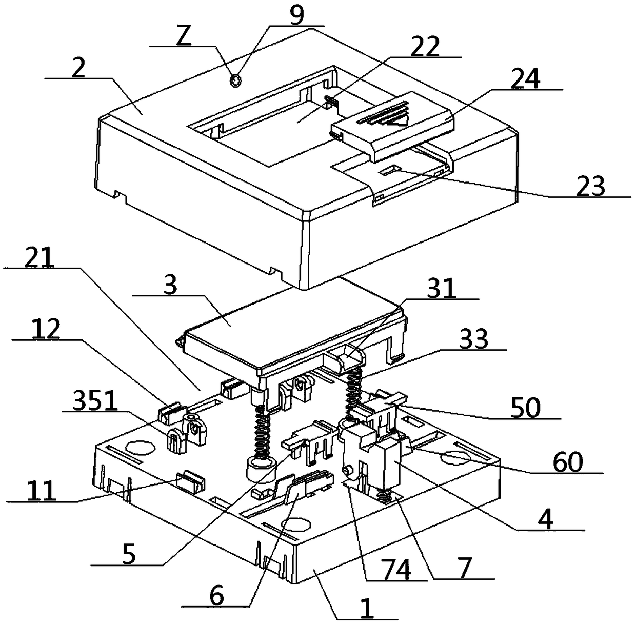
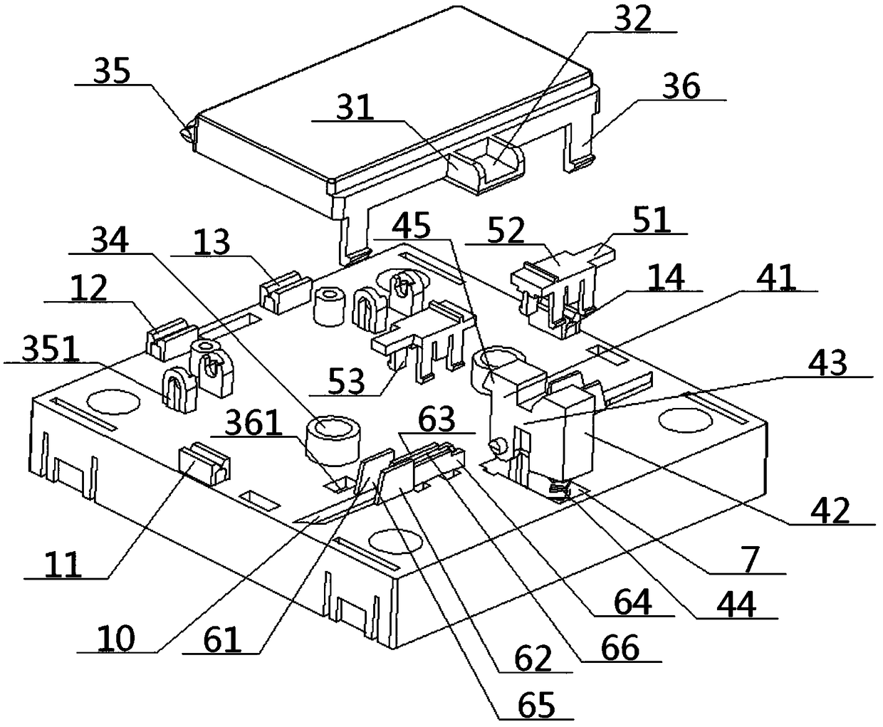
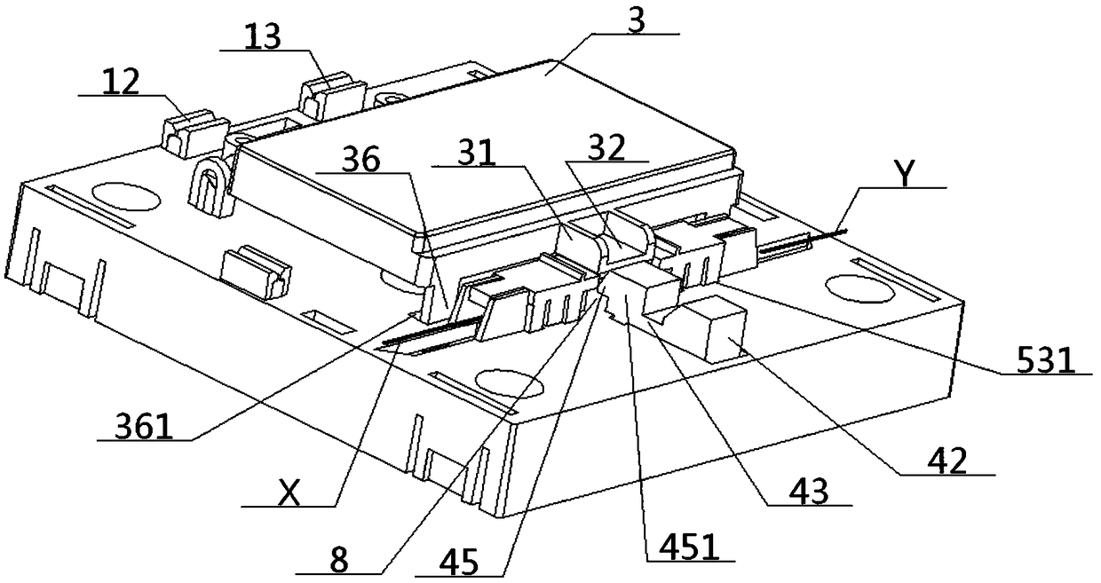
[0059] see figure 1 - Figure 8, an optical fiber manual fire alarm button, comprising a bottom case 1 and a face case 2 covered thereon, the face case 2 is provided with a touch panel 3 and a reset part 4 in an inter-shell cavity 21 covered above the bottom case 1 , and the top surface of the face shell 2 is provided with a touch port 22 and a reset port 23 corresponding to the touch panel 3 and the reset part 4; card frame 50, the top surface of the bottom shell 1 is provided with a left fiber card holder 6, a right fiber card holder 60, a reset slot 7 and a plate return column hole 34, the left fiber card holder 5 and the left fiber card The seat 6 is clamped up and down to clamp the left optical fiber X, and the right optical fiber clamp frame 50 and the right optical fiber clamp 60 are clamped up and down to clamp the right optical fiber Y arranged opposite to the left optical fiber X. The left optical fiber clamp 6 and the right An inter-seat area 8 is arranged between...

Embodiment 2

[0065] Basic content is the same as embodiment 1, the difference is:

[0066] A warning fiber hole 9 is arranged on the top surface of the face shell 2, and the trigger port 22 is located between the warning fiber hole 9 and the reset port 23, and a warning fiber Z connected to the fire alarm controller is inserted in the warning fiber hole 9.

[0067] In normal operation steps, the fire alarm controller controls the warning optical fiber Z to emit flashing light at a certain frequency as an indication of normal operation;

[0068] In the alarm operation step, after the convex cavity 31 cuts off the optical path between the left optical fiber X and the right optical fiber Y, the fire alarm controller controls the warning optical fiber Z to emit a constant light as an indication of the alarm operation.

Embodiment 3

[0070] Basic content is the same as embodiment 1, the difference is:

[0071] The two ends of described middle beam 43 are vertically connected with the middle part of front vertical column 41 and rear vertical column 42 respectively, and the inside of rear vertical column 42 is provided with rear column cavity 46 to insert and cooperate with the top of reset elastic member 44, reset The bottom of the elastic member 44 extends out of the rear vertical column 42 and is inserted into the rear vertical groove 72 . The front vertical column 41 includes a front left column plate 47 parallel to each other, a rear left column plate 48 and a front panel cavity 49 sandwiched between the two. The outer surfaces of the front left column plate 47 and the rear left column plate 48 are uniform. Be connected with a front rotating shaft 471, and this front rotating shaft 471 and the front half groove 74 that offers on the inwall of front vertical groove 71 carry out rotational cooperation, th...


PUM


Abstract

The invention discloses an optical fiber manual fire alarm button. The button includes a base shell, a face shell, a touch panel, a reset part, optical fiber clamping racks and optical fiber clampingseats; the two sets of the optical fiber clamping racks and optical fiber clamping seats are in corresponding clamp connection to clamp optical fibers; left and right optical fibers are in opposite arrangement; a seat intermediate zone is arranged between the left and right optical fiber clamping seats; the upper part of the seat intermediate zone is an outwards convex groove arranged on the sidepart of the touch panel; the side part of the seat intermediate zone is in opposite arrangement with a reset groove; the reset part is arranged in the reset groove; and an outwards convex hook on thereset part can suppress and release the outwards convex groove, so that the partition and conduction of an optical path between the left and right optical fibers can be realized, and fire alarm and reset can be realized as well. A manual fire alarm button function can be realized in a pure optical mode, so that electromagnetic interference, moisture and contact resistance change defects caused byelectronic components and copper wires can be avoided, and alarm effects can be ensured; and the button is easy to operate, so that low production, application and maintenance costs can be achieved.

Description

technical field [0001] The invention relates to a fire alarm button, in particular to an optical fiber manual fire alarm button and its use method, which is particularly suitable for eliminating electronic components and copper wires, so as to avoid electromagnetic interference, moisture, and contact resistance change defects, so as to ensure the alarm Effect. Background technique [0002] With the rapid development of the economy and urban construction, the scale of the city continues to expand and the population continues to increase. As a result, the probability of various types of fires, especially major vicious fires, is increasing year by year. Timely and effective fire detection and alarm signals are reduced. One of the most effective means of fire accident casualties and reduce economic losses, and the most effective and direct way of on-site alarm is to press the manual fire alarm button to start the sound and light alarm. [0003] Traditional manual fire alarm but...

Claims


Application Information

Patent Timeline
Patent Type & Authority Applications(China)
IPC IPC(8): G08B25/12
CPCG08B25/12
Inventor 张森
Owner 深圳晶点光科有限公司
Features
  • R&D
  • Intellectual Property
  • Life Sciences
  • Materials
  • Tech Scout
  • Unparalleled Data Quality
  • Higher Quality Content
  • 60% Fewer Hallucinations
Learn More