
An electromagnetic wave oscillator

An electromagnetic wave and oscillator technology, which is applied in the field of microwave electric vacuum devices, can solve problems such as increased emission non-uniformity, reduced cathode life, and heat dissipation difficulties, and achieves the effects of improving emission stability, increasing cathode life, and large heat dissipation area

Active Publication Date: 2020-04-14
UNIV OF ELECTRONICS SCI & TECH OF CHINA
View PDF5 Cites 2 Cited by
  • Summary
  • Abstract
  • Description
  • Claims
  • Application Information

AI Technical Summary

Problems solved by technology

However, as the power increases, the linear beam oscillator also has some disadvantages: 1) the cathode emission current density is high, the loss is serious, the cathode life is reduced and the emission non-uniformity is increased at the same time; 2) the electron beam interaction transmission distance is long, Difficulty in focusing; 3) Difficulty in heat dissipation

Method used


Image

  • An electromagnetic wave oscillator
  • An electromagnetic wave oscillator
  • An electromagnetic wave oscillator

Examples


Embodiment Construction

[0016] Specific embodiments of the present invention will be described below in conjunction with the accompanying drawings, so that those skilled in the art can better understand the present invention. It should be noted that in the following description, when detailed descriptions of known functions and designs may dilute the main content of the present invention, these descriptions will be omitted here.

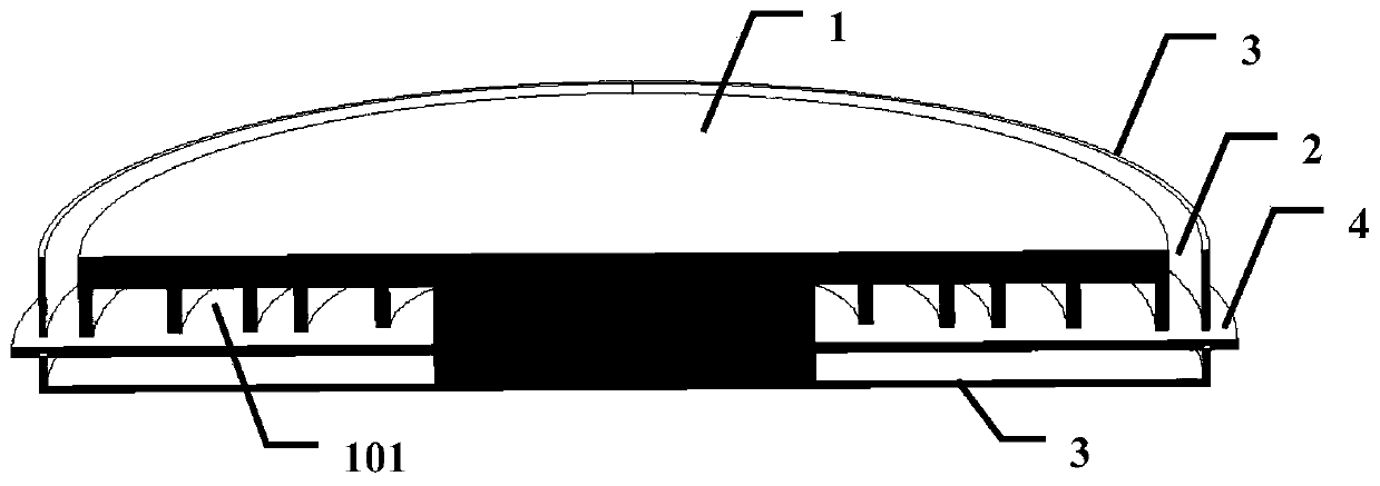
[0017] figure 1 It is a structural schematic diagram of a specific embodiment of the electromagnetic wave oscillator of the present invention.

[0018] In this example, if figure 1 As shown, the electromagnetic wave oscillator of the present invention includes a metal ring 1 , a cathode (not shown), an output structure 2 and a casing 3 .

[0019] One annular surface of the metal ring 1, in this embodiment, the lower annular surface is engraved with five concentric circular grooves 101 with different radii.

[0020] In this embodiment, it is placed on the edge of one side...


PUM


Abstract

The invention discloses an electromagnetic wave oscillator, which includes a metal ring, a cathode and an output structure. By engraving concentric circular grooves with different radii on one ring surface of the metal ring, the cathode placed at the edge or center of the metal ring generates The electron beam on the inner or outer edge, the electron beam interacts with the concentric circular slots to generate electromagnetic waves, which are output through the output structure. Compared with the linear electron beam, the cathode emission density is lower, and the loss to the cathode is small, which can improve the cathode life and emission stability; the electron movement direction of the electron beam is consistent with or opposite to the direction of the space charge force, so no focusing is required; at the same time , the heat generated can be dissipated through the metal edge, and the heat dissipation area is large, which can dissipate heat quickly.

Description

technical field [0001] The invention belongs to the technical field of microwave electric vacuum devices, and more specifically relates to electromagnetic wave oscillators in vacuum electronic devices such as traveling wave tubes, klystrons, and gyrotrons. Background technique [0002] The electromagnetic wave oscillator is a device that converts DC power into electromagnetic waves with a certain frequency. High-power and high-frequency electromagnetic wave oscillators have great application value in electronic countermeasures, advanced radar, and tactical defense. [0003] In the prior art, high-power and high-frequency electromagnetic wave oscillators use pulse power technology to generate high-voltage pulse signals, and then use diodes to convert high-voltage pulse signals into high-voltage strong-current electron beams, and the electron beams interact with slow-wave structures or resonant cavities to generate electromagnetic waves output. [0004] High-power high-frequ...

Claims


Application Information

Patent Timeline
Patent Type & Authority Patents(China)
IPC IPC(8): H01J23/00H01J23/04
CPCH01J23/005H01J23/04
Inventor 王战亮林嘉文李士锋宫玉彬段兆云巩华荣
Owner UNIV OF ELECTRONICS SCI & TECH OF CHINA
Learn More