
Injector laser

a laser and injector technology, applied in the field of optoelectronic technology, can solve the problems of large diffractional divergence of emission, increase of optical losses by emission output, and complexity in accuracy and repeatability, and achieve the effects of reducing emission optical losses, high reliability of operation, and increasing efficiency

Inactive Publication Date: 2010-08-31
GENERAL NANO OPTICS
View PDF6 Cites 0 Cited by
  • Summary
  • Abstract
  • Description
  • Claims
  • Application Information

AI Technical Summary

Benefits of technology

[0006]Technical results consist in the fact that the length of the proposed Laser is in principle unlimited (the indicated length is restricted only by the size of the used semi-conducting substrate), that the density of emission at the output facets of the Laser is significantly reduced (by the factor of 10−2-10−3), what stipulates a super-high power of laser emission, high efficiency, low optical losses of emission and their independence on the Laser length, low threshold current, low ohmic losses which are decreasing with increase of the Laser length, higher resource of operability and high reliability of the Laser and also that directivity and divergence of the output emission are controlled in a wide range and that the technological process of the Laser manufacture is simplified.
[0022]Essence of the present invention consists in creation in its integral execution of the new type of Laser with surface output of emission out of the active layer in particular in the form of the great number of beams. The said Laser is based on the proposed original effective and non-obvious way of the emission output using properties of the outflow emission. The original and effective emission output regions are introduced into the active region and are discretely distributed along the length of emitter (the length is in principle not limited). The said output regions secure super-high emission power with the high reliability of their operation as well as reduction of optical losses of emission and their independence on the Laser length, increase of efficiency, very significant reduction of the emission density (by the factor of 10−1-10−3) on the output facets, controlled directivity and divergence of the laser emission, reduced values of ohmic and thermal resistances and also significant simplification of the technological process of Laser manufacture.

Problems solved by technology

At the same time there are technological complexities in accuracy and repeatability by manufacture of the arrangements for emission output being executed in the form of narrow cavities in the heterostructure and located in the immediate vicinity of the active layer.
This can lead to a great diffractional divergence of emission at the output cells and correspondingly to increase of optical losses by output of emission and to decrease of its efficiency.
This fact can create difficulties by securing the necessary resources of operability and reliability.

Method used


Image

  • Injector laser
  • Injector laser
  • Injector laser

Examples


Embodiment Construction

[0033]In the following the invention will be explained by concrete versions of its execution with references to the enclosed drawings. The presented examples of the Laser modification aren't unique and allow presence of other realizations including wavelengths within certain ranges the features of which are reflected in the multitude of attributes of the Claims.

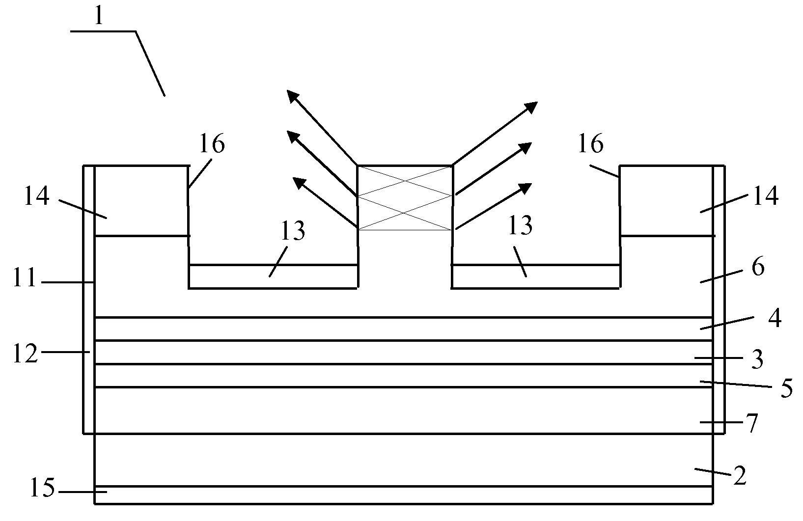
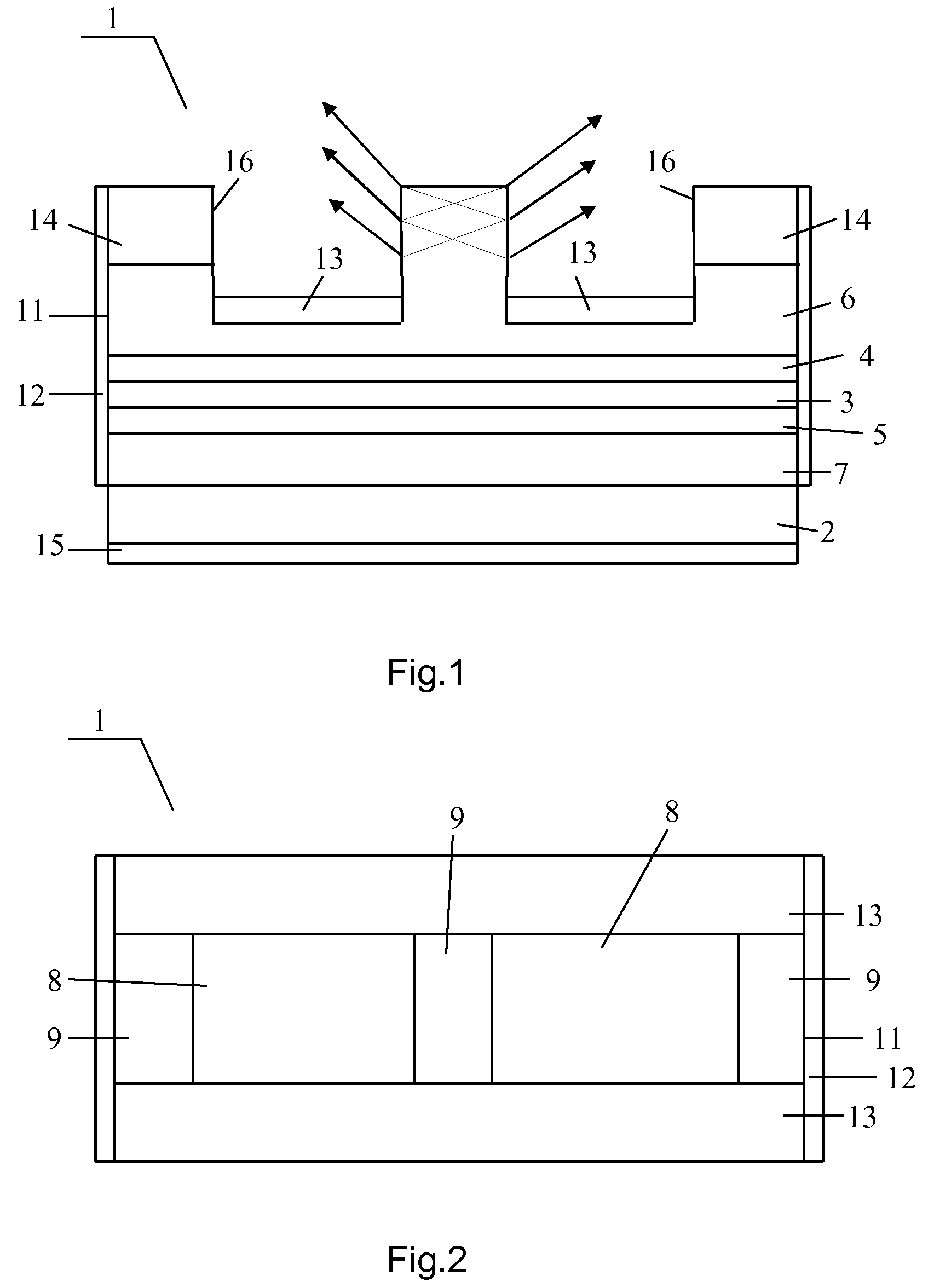
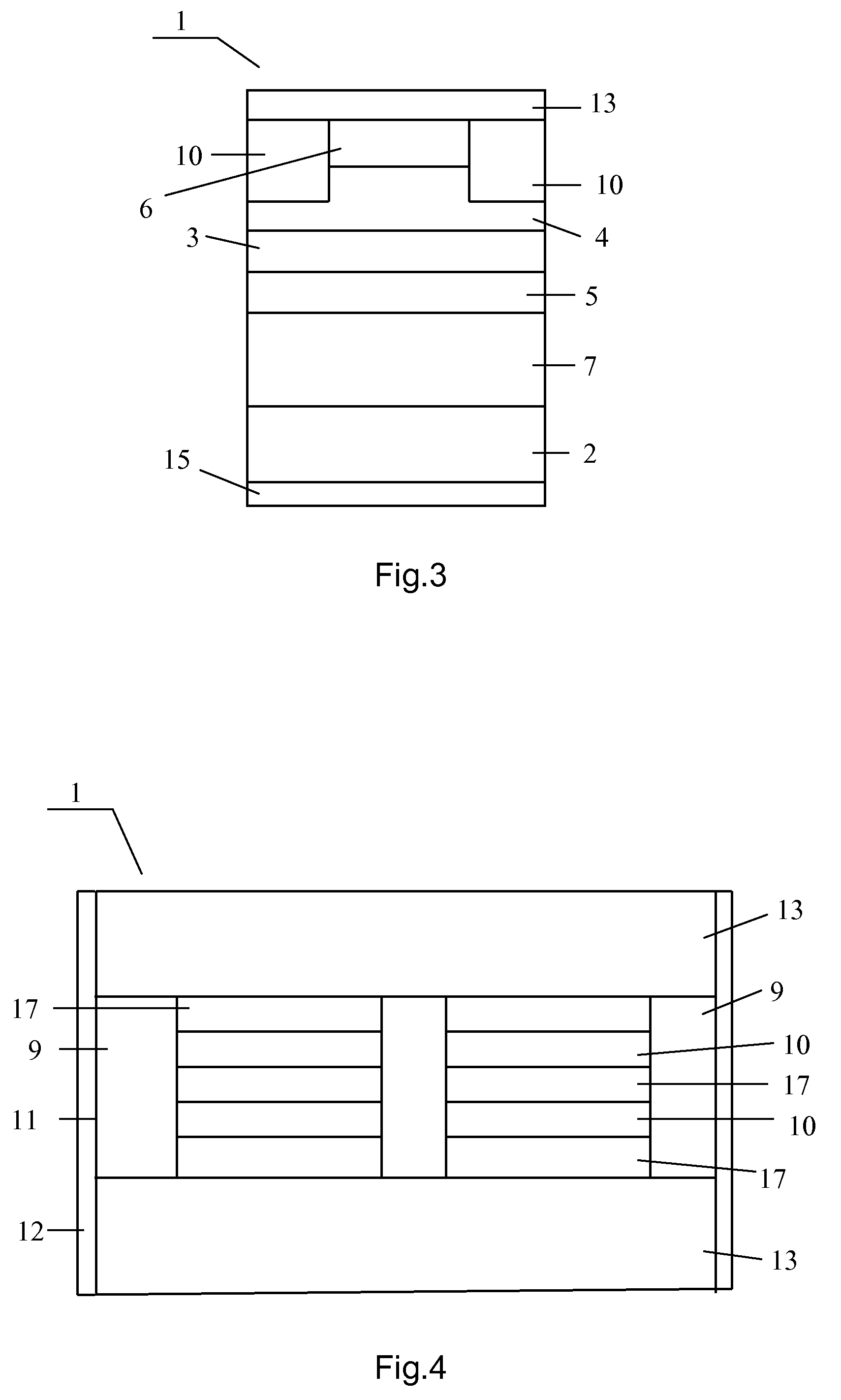
[0034]The proposed Laser 1 (see FIG. 1-3) contains the laser heterostructure placed on the substrate 2 of the n-type GaAs. The said heterostructure is made on the basis of compounds InAlGaAs with the active InGaAs layer 3, with the waveguide layers 4, 5 and the confining layers 6, 7 of AlGaAs, placed correspondingly on the side of emission output and on the side opposite to it. The wavelength of laser emission was chosen equal to 0.98 μm. The functional bar of the Laser 1 is executed as a stripe and consists of alternating amplification regions 8 and output regions 9. The said alternation goes along the longitudinal optical a...


PUM


Abstract

Injection radiators are used for pumping solid-state and fiber lasers and amplifiers used for producing medical devices, laser production equipment, lasers generating a double-frequency radiation and in the form of highly efficient general-purpose solid-state radiation sources used in a given waveband, including white light emitters used for illumination. Said invention also relates to superpower highly-efficient and reliable injection surface-emitting lasers, which generate radiation in the form of a plurality of output beams and which are characterised by a novel original and efficient method for emitting the radiation through the external surfaces thereof.

Description

FIELD OF THE INVENTION[0001]The invention relates to optoelectronic technology, namely—to the effective powerful and compact semiconducting injection lasers (diode lasers) operating in a broad range of wavelengths.DESCRIPTION OF THE RELATED ART[0002]Various types of injection lasers are known: the injection lasers with a stripe active region of generation and with the output of emission through the edge mirror of the optical resonator [S. S. Ou et al., Electronics Letters (1992). v. 28, No. 25, pp. 2345-2346], the surface-emitting injection lasers with the vertical resonator [A. Krigge et al., Electronics Letters, 2001, vol. 37, No. 20, pp. 1222-1225], the injection lasers with the outgoing emission in the optical resonator [Shveykin V. I., U.S. Pat. No. 6,748,002 B2, Jun. 8, 2004].[0003]From the standpoint of technical substance and technical problem to be solved the closest the injection laser-prototype with a surface emission was described in the following work [Sveykin V. I., Pa...

Claims


Application Information

Patent Timeline
Patent Type & Authority Patents(United States)
IPC IPC(8): H01S5/00H01S5/185
CPCH01S5/18H01S5/1032H01S5/1039H01S5/187H01S5/2211H01S5/42H01S5/185H01S5/00
Inventor SHVEYKIN, VASILY IVANOVICH
Owner GENERAL NANO OPTICS
Learn More