Injector Laser

Inactive Publication Date: 2008-08-14
GENERAL NANO OPTICS
2 Cites 1 Cited by

AI-Extracted Technical Summary

Problems solved by technology

At the same time there are technological complexities in accuracy and repeatability by manufacture of the arrangements for emission output being executed in the form of narrow cavities in the heterostructure and located in the immediate vicinity of the active layer.
This can le...

Benefits of technology

[0022]Essence of the present invention consists in creation in its integral execution of the new type of Laser with surface output of emission out of the active layer in particular in the form of the great number of beams. The said Laser is based on the proposed original effective and non-obvious way of the emission output using properties of the outflow emission. The original and effective emission output regions are introduced into the active region and are discretely distributed along the length of emitter (the length is in prin...

Abstract

Injection radiators are used for pumping solid-state and fibre lasers and amplifiers used for producing medical devices, laser production equipment, lasers generating a double-frequency radiation and in the form of highly efficient general-purpose solid-state radiation sources used in a given waveband, including white light emitters used for illumination. Said invention also relates to superpower highly-efficient and reliable injection surface-emitting lasers, which generate radiation in the form of a plurality of output beams and which are characterised by a novel original and efficient method for emitting the radiation through the external surfaces thereof.

Application Domain

Laser optical resonator constructionExcitation process/apparatus +1

Technology Topic

InjectorWhite light +11

Image

  • Injector Laser
  • Injector Laser
  • Injector Laser

Examples

  • Experimental program(1)

Example

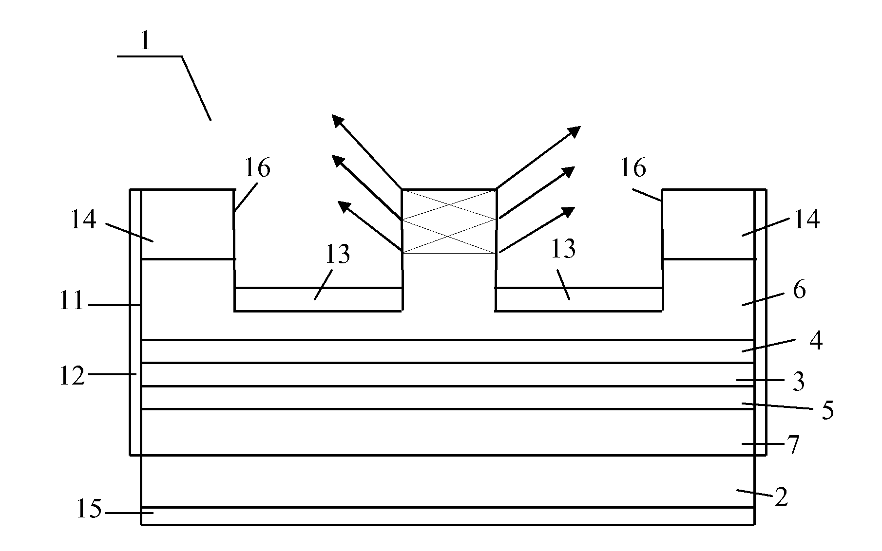
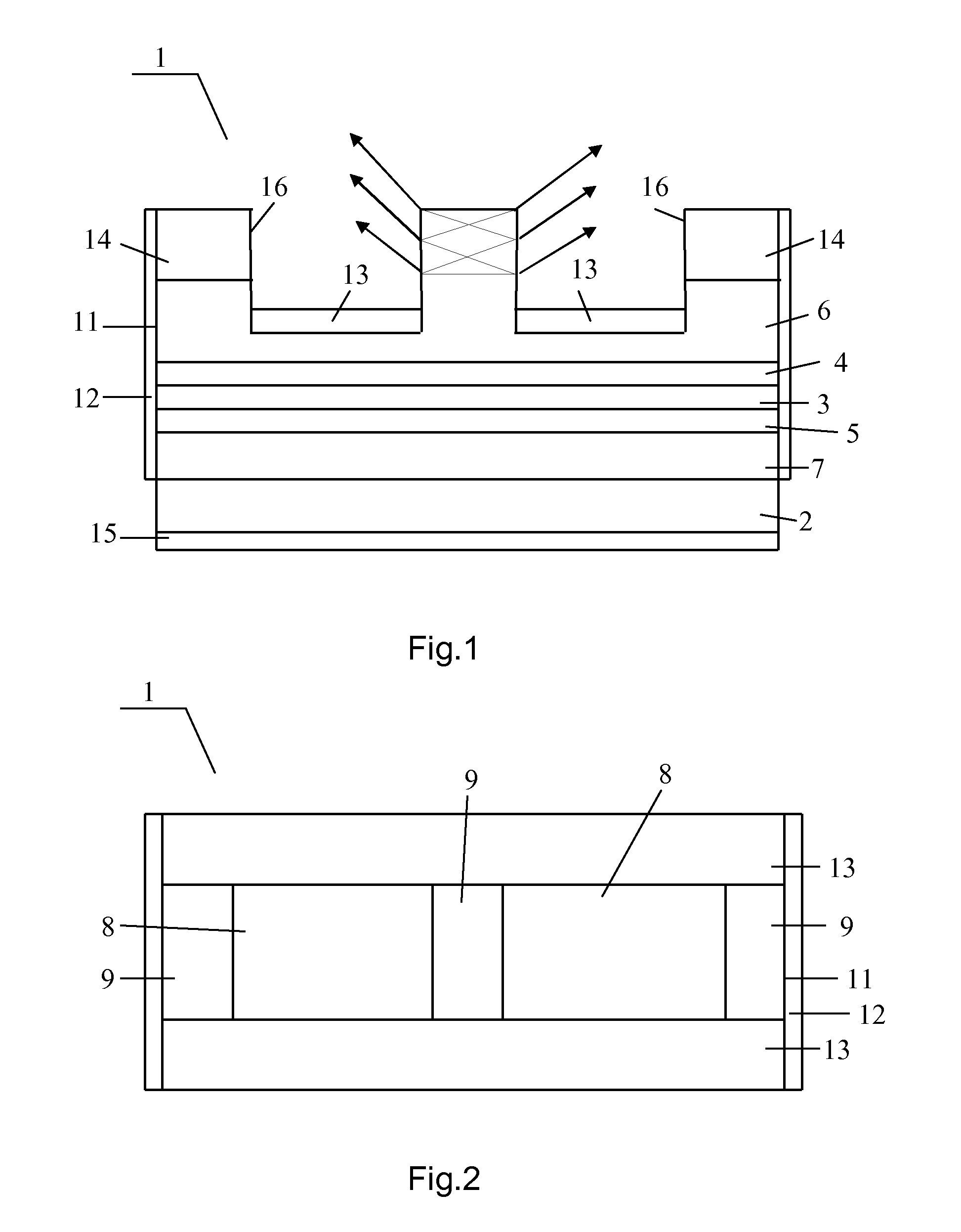
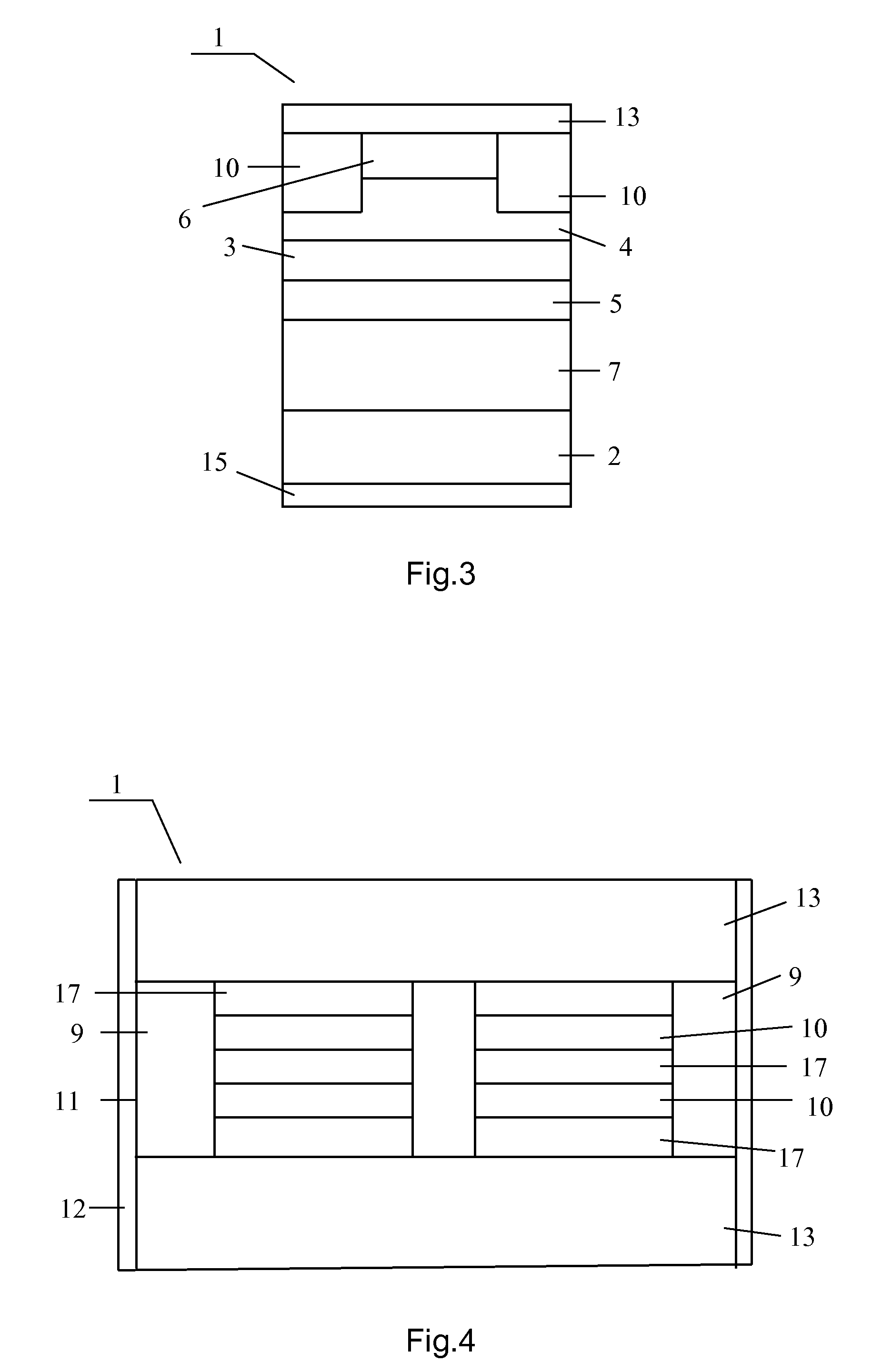
[0033]In the following the invention will be explained by concrete versions of its execution with references to the enclosed drawings. The presented examples of the Laser modification aren't unique and allow presence of other realizations including wavelengths within certain ranges the features of which are reflected in the multitude of attributes of the Claims.
[0034]The proposed Laser 1 (see FIG. 1-3) contains the laser heterostructure placed on the substrate 2 of the n-type GaAs. The said heterostructure is made on the basis of compounds InAlGaAs with the active InGaAs layer 3, with the waveguide layers 4, 5 and the confining layers 6, 7 of AlGaAs, placed correspondingly on the side of emission output and on the side opposite to it. The wavelength of laser emission was chosen equal to 0.98 μm. The functional bar of the Laser 1 is executed as a stripe and consists of alternating amplification regions 8 and output regions 9. The said alternation goes along the longitudinal optical axis. The width values amplification regions 8 and output regions 9 are identical and equal to 100 μm. The lateral sides of the said regions 8 and 9 are restricted by the lateral confining regions 10 of ZnSe. On the edge facets 11 the film reflectors 12 of the optical resonator Fabry-Perot with the reflection coefficient 99% were formed. On the side of the emission output the thickness and composition of the confining layer 6 in the amplification region 8 were chosen in such a way that partial restriction of emission in the heterostructure is realized. To the external surface of the amplification regions 8 the metallization sublayer 13 is attached made of silver with the reflection coefficient of emission equal to 98%. The output region 9 contains the additional semi-conducting leak-in layer 14 of GaAs the distinctive feature of which consists in the fact that its refraction index nIN exceeds the effective refraction index neff of the laser heterostructure with the leak-in layer 14 included into it. Connection by the current of all amplification regions 8 is realized by expansion the metallization layer 13 not only to the external surface of the amplification regions 8 but also to the lateral confining regions 10 (the expansion contact of the amplification regions 8). Corresponding metallization layer 15 is also applied to the substrate 2. The output facets 16 confining the output region 9 along the longitudinal amplification axis are perpendicular to the external surface of the amplification region 9 and at that the angles α1 are by absolute values equal to the angles α2 and are equal to 90°. In this case the output regions 9 raising above the external surface of the amplification regions 8 have the form of the rectangular parallelepiped. The length of the Laser 1 is chosen equal to 20010 μm. The lengths of the amplification regions 8 and the output regions 9 were chosen equal to 90 μm and 10 μm correspondingly. At that the numbers of the regions 8 and the output regions 9 formed in the functional bar are equal to 200 and 201 correspondingly. The output emission of the Laser 1 consists of 400 beams a half of which is directed in one direction along the longitudinal amplification axis and another half of which is directed in the opposite direction. For this modification of the Laser 1 the outflow angle φ was set equal to 10° through appropriate choice of compositions and thickness values of the layers of heterostructure and of the leak-in layer 14. At that the refraction angle β for the output beams is equal to 30°. The chosen thickness of 6.0 μm of the emission output regions 9 is approximately equal to the triple value of the product of the length of the output region 9 by the tangent of the outflow angle φ. In this case the calculated portion of the output emission by thrice-repeated incidence of beams on the output facet 16 contains 98%. The diffraction divergence of every beam is approximately equal to 9°. The calculated power of the output emission PEM is equal to 200 W (by 0.5 W for every output beam). At that the average density of emission on the output facet 16 makes up totally 125 kW/cm2. The differential efficiency ηH is equal to 85%. The efficiency factor (coefficient of efficiency from the outlet) is equal to 80%.
[0035]The following modification of the Laser 1 differed from the previous one by the fact that on the side of one edge facet 11 the introduced reflector (not shown in the figures) with the sizes allowing to reflect all laser beams directed to it is connected. At that the total laser emission with low divergence is formed as unidirectional emission to the side of the opposite edge under the angle β equal to 30° with respect to the longitudinal amplification axis.
[0036]The following modification of the Laser 1 differed from the modification shown in the FIG. 1-3 by the fact that the Laser 1 contained only one output region 9 located between two identical amplification regions 8 with the corresponding enlarged size of the regions.
[0037]The next modification of the Laser 1 (see FIG. 4) differed from the modification shown in the FIG. 1-3 by the fact that every amplification region 8 consisted of ten (in the FIG. 4 of three) located in parallel stripe amplification subregions 17 with the width of 10 μm each and the placed between them lateral confining regions 10 with the width of 5 μm each filled by the sprayed dielectric ZnSe up to the appropriate optimum depth. Over the stripe subregions 17 and the lateral confining regions 10 metallization layers 13 are applied (not shown in the FIG. 4).
[0038]The following modification (see FIG. 5) differed from the modification of the Laser 1 shown in the FIG. 1-3 by the fact that in the middle of every output region 9 along the total length the additional amplification regions 18 of the stripe form were formed with the corresponding metallization layers 13 (not shown in the FIG. 5, both on the amplification regions 8 and 18 and also on the output regions 9) connecting by the current the amplification regions 8 along all length of the Laser 1 equal to 20010 μm. By that the width of the introduced additional generation regions is equal to 4 μm.
[0039]The proposed Laser 1 (see FIG. 6-8) differed from modification of the Laser 1 shown in the FIG. 1-3 by the fact that on the side opposite to the side of emission output the substrate 2 is removed and thickness and composition of the confining layers 6 and 7 were chosen in such a way that a partial restriction of emission in the heterostructure is realized. At that to the external surfaces of the confining layers 6 and 7. the corresponding metallization layers 13 and 19 including silver sublayers were connected. The said layers 13 and 19 includes the layers of silver with the emission reflection coefficient equal to 98%. On the side opposite to the emission output side the Laser 1 is connected to the conducting plate 20 of CuW together with which it is placed on the copper heat-removing base (not shown in the figures). Besides corresponding metallization layers 21 are connected to the leak-in layer 14 of the output regions 9. Connection by the current of all output regions 9 is executed through expansion of the metallization layers 21 (by the level of leak-in layers 14) onto one of the lateral sides of the Laser 1 (expanded autonomous contact of the output regions 9).
[0040]The following modification of the Laser 1 differed from the previous one by the fact that the above indicated metallization layers 13 and 19 were connected directly to the waveguide layers 4 and 5.
[0041]The proposed Laser 1 (see FIG. 9) differed from modification of the Laser 1 shown in the FIG. 1-3 by the fact that the output facets 16 confining the output regions 9 along the longitudinal amplification axis were executed as inclined to the external surface of the amplification region 8 and at that the angles α1 by absolute value are equal to the angles α2 and are equal to 100°. In this case the output region 9 has the form of trapezium in its longitudinal section. For increase of efficiency of the Laser 1 antireflecting optical coatings (not shown in the figure) are applied on the output facets 16 of the output regions 9. Thickness of the leak-in layer 14 in the output region 9 was chosen equal to 2.0 μm. In this modification every laser beam falls under the right angle on the inclined facet 16 and straightly goes out of the Laser 1.
[0042]The following modification differed from the previous one by the fact that optical coatings (not shown in the figures) with the reflection coefficient of 99% are applied on the output facets 16 the output emission from which is directed into one of the selected (one of two) directions.
[0043]The following modification of the Laser 1 (see FIG. 10) differed from the modification of the Laser 1 shown in the FIG. 9 by the fact that the output facets 16 are executed with the inclined form and at that the angles α1 by their absolute value are equal to the angles α2 and are equal to 50°. In this case the output region 9 has the form of upturned trapezium in the longitudinal section. Thickness of the output regions 9 is equal to 2.2 μm. In this modification the output emission undergoes total internal reflection of the inclined output facets 16, changes its direction and goes out along the edges of the external surface of the leak-in layers 14 by direct incidence on them.
[0044]The following modification of the Laser 1 (see FIG. 11) differed from the previous one by the fact that the output facets 16 are executed with the inclined form and at that the angles α1 by their absolute values are equal to the angles α2 and are equal to 140°. In this case the output regions 9 have the form of trapezium in the longitudinal section and thickness of the output regions 9 was chosen equal to 1.7 μm. In this modification the output leaky emission undergoes total internal reflection of the inclined output facets 16 changes its direction and goes out through the substrate 2 transparent for emission by direct incidence upon it. Antireflecting optical coatings are applied on the substrate in places of output of the emission.
INDUSTRIAL APPLICABILITY
[0045]Injection lasers are used for pumping solid-state and fiber lasers and amplifiers, in the medical apparatus, laser technological equipment, lasers with doubled frequency of the generated emission and also are used as high-efficient powerful solid-state emission sources of wide application in the certain range of wavelengths including emitters of white light for lighting.

PUM

no PUM

Description & Claims & Application Information

We can also present the details of the Description, Claims and Application information to help users get a comprehensive understanding of the technical details of the patent, such as background art, summary of invention, brief description of drawings, description of embodiments, and other original content. On the other hand, users can also determine the specific scope of protection of the technology through the list of claims; as well as understand the changes in the life cycle of the technology with the presentation of the patent timeline. Login to view more.

Similar technology patents

Filtering Device

InactiveUS20120282146A1improve longevityreliable in operation
Owner:PASSLER KARLHEINZ

Wide angle oval light emitting diode package

Owner:CREE HUIZHOU SOLID STATE LIGHTING

Switch

Owner:PANASONIC CORP

Classification and recommendation of technical efficacy words

  • increase efficiency
  • reliable in operation
Why Eureka
Try Eureka