A High Frequency Band Magnetic Insulated Wire Oscillator

A magnetic insulation and oscillator technology, applied in the field of microwave sources, can solve the problems of slow microwave vibration and saturation of devices, waste of input electric pulse width, and inability of electron beams to pass through, reducing radio frequency fields, improving power capacity, and reducing cathodes. Electron emission uniform effect

Active Publication Date: 2017-05-24
NAT UNIV OF DEFENSE TECH
View PDF5 Cites 0 Cited by
  • Summary
  • Abstract
  • Description
  • Claims
  • Application Information

AI Technical Summary

Problems solved by technology

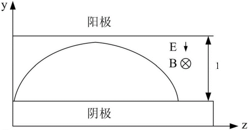
However, there is a problem with the structure of the traditional low-frequency MILO used in the high-frequency band MILO: the electron beam emitted at the starting point of the cathode cannot pass over the surface of the first cavity of the main slow-wave structure, which will make the device start-up and saturation slower
Because the blade radius of the choke cavity is smaller than the inner radius of the blade of the slow-wave structure, the electron beam emitted at the starting point of the cathode cannot pass over the surface of the first cavity of the main slow-wave structure after passing over the structure of the choke cavity, which will Slow microwave start-up and saturation of the device
However, the slow microwave start-up and saturation in the microwave source will cause waste of the input electrical pulse width, making the output microwave pulse width of the microwave source device shorter and the energy efficiency lower
[0010] Therefore, the study of high-frequency MILO has important practical significance, and the problem of slow start-up and saturation of high-frequency MILO still needs further research

Method used


Image

  • A High Frequency Band Magnetic Insulated Wire Oscillator
  • A High Frequency Band Magnetic Insulated Wire Oscillator
  • A High Frequency Band Magnetic Insulated Wire Oscillator

Examples


Embodiment Construction

[0032] The specific implementation manners of the present invention will be further described below in conjunction with the accompanying drawings.

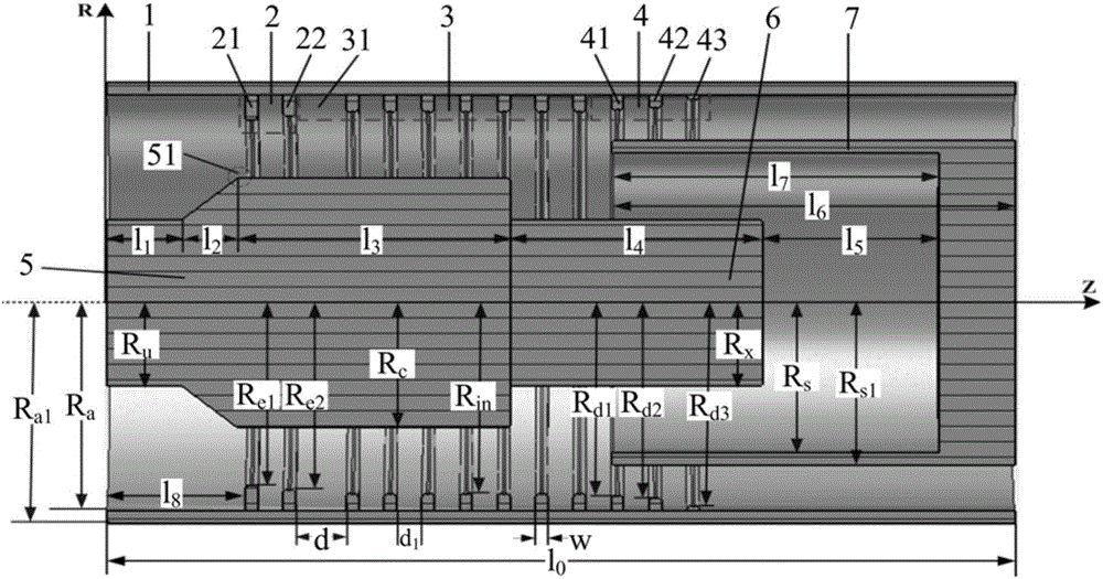
[0033] figure 2 It is a longitudinal sectional view of a high-frequency magnetic insulated line oscillator (MILO) of the present invention, for the convenience of description, define figure 2 The Z-axis direction is the axial direction, and the R-axis direction is the radial direction.

[0034] The high-frequency magnetic insulated line oscillator (MILO) of the present invention is a circumferentially symmetrical coaxial structure, consisting of an outer cylinder 1, a gradual choke cavity structure 2, a main slow wave structure 3, an extraction cavity structure 4, a cathode 5, and a load cathode 6 And electron collector (loaded anode) 7 composition. The outer cylinder 1 is coaxial with the gradual choke cavity structure 2, the main slow wave structure 3, the extraction cavity structure 4, the cathode 5, the load cathode 6 and ...


PUM


Abstract

The invention belongs to the technical field of microwave sources in high power microwave technology, and specifically relates to a high band magnetically insulated transmission line oscillator with fast microwave oscillation starting and saturation and high power capacity. The high band magnetically insulated transmission line oscillator provided by the invention is of a circular symmetry coaxial structure and is composed of an outer cylinder, a gradient choke cavity structure, a main slow wave structure, an extraction cavity structure, a cathode, a carrier cathode and an electron collector. According to the high band magnetically insulated transmission line oscillator provided by the invention, since the gradient choke cavity structure is adopted, and the distance of first interaction cavities is increased, an electron beam emitted by a starting point of the cathode can pass by the surface of a first cavity, and fast microwave oscillation starting and saturation can be realized; moreover, the high band magnetically insulated transmission line oscillator provided by the invention can effectively reduce a radio frequency field, reduce the radio frequency breakdown risk of the slow wave structure and effectively improve the power capacity of the devices; and the high band magnetically insulated transmission line oscillator provided by the invention further increases the length of the cathode, can reduce the average emission current density of the cathode and is conducive to improving the electron emission uniformity on the surface of the cathode and prolonging the service life of the cathode. These improvements have important significance of improving the output power and pulse width of high ban MIMO.

Description

technical field [0001] The invention belongs to the technical field of microwave sources in high-power microwave technology, and in particular relates to a high-frequency band magnetic insulated wire oscillator with fast microwave start-up and saturation and high power capacity. Background technique [0002] Magnetically insulated transmission line oscillator (MILO for short) is a GW-level high-power microwave source. Compared with other microwave sources, MILO has become one of the most promising HPM devices because it does not require an external guiding magnetic field, and has the advantages of compact structure and light weight. [0003] Pf 2 The factor (the product of the microwave power P and the microwave frequency f square) is used as a measure of the performance of high-power microwave devices, which means that the power density of the microwave signal emitted from the fixed-size antenna acting on the target is proportional to the factor. In this sense, the increa...

Claims


Application Information

Patent Timeline
Patent Type & Authority Patents(China)
IPC IPC(8): H01J23/24H03B13/00
CPCH01J23/24H03B13/00
Inventor 江涛张建德贺军涛李志强
Owner NAT UNIV OF DEFENSE TECH
Why Eureka
Try Eureka