Crystal oscillator circuit based on phase-locked loop injection

A crystal oscillator, phase-locked loop technology, applied in electrical components, impedance networks, etc., can solve problems such as energy waste, achieve large output swing, solve the effect of inaccurate injection frequency, and good phase noise

Inactive Publication Date: 2021-03-09
NANJING UNIV OF POSTS & TELECOMM
View PDF4 Cites 0 Cited by
  • Summary
  • Abstract
  • Description
  • Claims
  • Application Information

AI Technical Summary

Problems solved by technology

When the injection frequency matches the frequency of the crystal oscillator, CI charges the crystal instantaneously, but a lot of energy is wasted during the CI phase

Method used


Image

  • Crystal oscillator circuit based on phase-locked loop injection

Examples


Embodiment Construction

[0015] The specific implementation manners of the present invention will be further described in detail below in conjunction with the accompanying drawings.

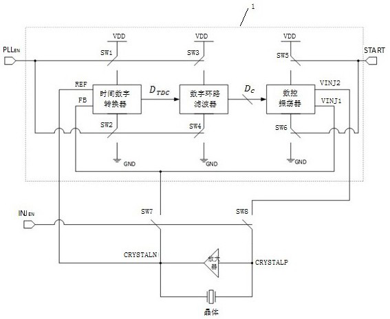
[0016] Such as figure 1 As shown, a kind of crystal oscillator circuit based on phase-locked loop injection designed by the present invention includes crystal, amplifier, the seventh switch SW7, the eighth switch SW8, and digital phase-locked loop 1; one end CRYSTALP of the crystal and the amplifier The input end of the eighth switch SW8 is connected; the other end CRYSTALN of the crystal is connected with the output end of the amplifier, the output end of the seventh switch SW7, and the reference clock input end REF of the digital phase-locked loop; The input end of the seventh switch SW7 is connected to the differential oscillation signal output end VINJ1 of the digital phase locked loop; the input end of the eighth switch SW8 is connected to the differential oscillation signal output end VINJ2 of the digital phase locke...


PUM


Abstract

The invention relates to a crystal oscillator circuit based on phase-locked loop injection, which adopts a quickly locked digital phase-locked loop, and comprises the following steps of: firstly, injecting the output of a numerical control oscillator into a crystal to realize the first-step energy injection, then, using a crystal oscillator as a reference clock of the phase-locked loop to realizethe second-step energy injection, and therefore, the frequency and the phase of the numerical control oscillator are locked as the frequency and the phase of the crystal oscillator, and then second-step energy injection is performed on the crystal, so that the crystal starts oscillation quickly in a short time, relatively large output swing and relatively good phase noise are realized on the premise of ensuring low power consumption, and the problem that the injection frequency of a traditional oscillator is inaccurate is solved.

Description

technical field [0001] The invention relates to a crystal oscillator circuit based on phase-locked loop injection, which belongs to the technical field of integrated circuits. Background technique [0002] With the rapid development of Internet of Things technology, wearable devices and sensor nodes are widely used in various fields such as military, biomedicine and environmental detection. These devices and sensor nodes are generally powered by batteries. Due to the constraints of device size and battery technology, in order to reduce the power consumption of such chips, the system often works periodically and stays in sleep mode for a long time, only when it needs to transmit or receive data. The wake-up will only be performed when the clock circuit of the chip is included. The crystal oscillator is often used as the clock source of the chip because of its stable frequency characteristics, but it takes hundreds of microseconds for the crystal oscillator to stabilize and o...

Claims


Application Information

Patent Timeline
Patent Type & Authority Applications(China)
IPC IPC(8): H03H9/17H03H9/02
CPCH03H9/02H03H9/17
Inventor 蔡志匡储奕锋周毅王子轩金招省郭宇锋
Owner NANJING UNIV OF POSTS & TELECOMM
Why Eureka
Try Eureka