An electric power system for charging a power supply

A power system and power supply technology, applied to battery circuit devices, current collectors, electric vehicles, etc., can solve problems such as waste of electricity in the power system, damage to the power system, protection of electrical equipment and transmission lines, etc.

Inactive Publication Date: 2019-01-04
广东南控电力有限公司
View PDF5 Cites 2 Cited by
  • Summary
  • Abstract
  • Description
  • Claims
  • Application Information

AI Technical Summary

Problems solved by technology

When the power system charges the power storage equipment used by the user, it is only directly connected to the power supply through the plug, without protecting the electrical equipment and transmission lines, which is likely to cause waste of electricity in the power system and damage to the power system

Method used


Image

  • An electric power system for charging a power supply
  • An electric power system for charging a power supply
  • An electric power system for charging a power supply

Examples


Embodiment 1

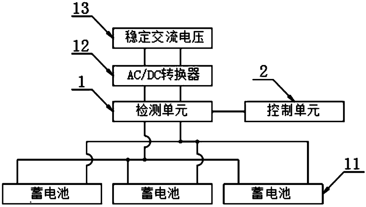
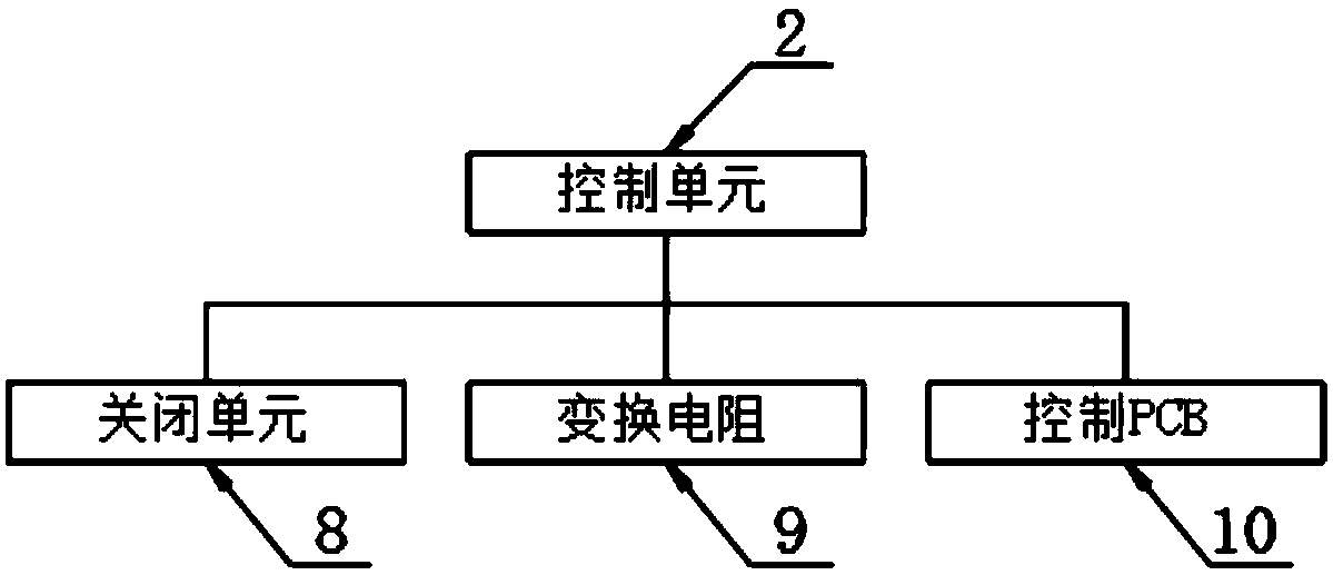
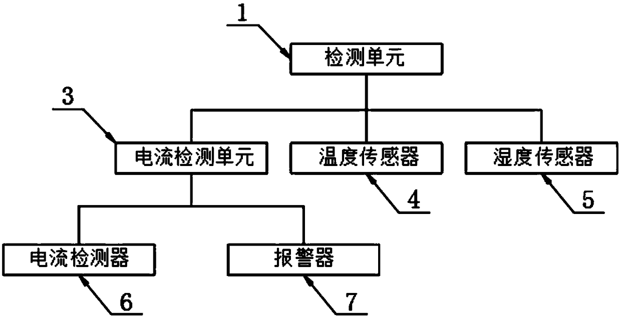
[0023] The present invention provides such Figure 1-4 The power system for power charging shown includes a detection unit 1 and a control unit 2. The detection unit 1 includes a current detection unit 3, a temperature sensor 4 and a humidity sensor 5. The temperature sensor 4 mainly checks the AC / DC conversion The humidity sensor 5 mainly detects the humidity of the environment where the AC / DC converter 12 and the storage battery 11 are located, and uses the control unit 2 to close the current passing through the detection unit 1, thereby protecting the power transmission itself. The detection unit 3 includes a current detector 6 and an alarm 7, the control unit 2 includes a closing unit 8, a conversion resistor 9 and a control PCB 10, the output of the detection unit 1 is provided with a storage battery 11, and the detection unit 1 and the storage battery 11 Connected by a energized cable, the input end of the detection unit 1 is provided with an AC / DC converter 12, and the ...

Embodiment 2

[0029] The stable AC voltage 13 is connected to the AC / DC converter 12 through a cable, and the AC / DC converter 12 conveniently converts the AC power of the stable AC voltage 13 into a DC power, and the AC / DC converter 12 is electrically connected to the detection unit 1 The connection is convenient and the detection unit 1 can detect the current passing through the circuit and the accessory electrical appliances in the circuit.

[0030] The detection unit 1 is electrically connected with the control unit 2, which is convenient for the control unit 2 to adjust the detection result of the detection unit 1 and protect the circuit. The temperature sensor 4, humidity sensor 5 and current detector 6 are all connected with the AD converter 14 are electrically connected, the AD converter 14 converts the transmitted electrical signal into a convenient digital signal for CPU15 calculation, the temperature sensor 4 model is set to GMD50, the humidity sensor 5 model is set to HH-4000-003,...


PUM


Abstract

An electric power system for charging a power supply includes a detection unit and a control unit, the detection unit includes a current detection unit, a temperature sensor and a humidity sensor, thetemperature sensor mainly checks the temperature of the AC / DC converter, the humidity sensor mainly detects the humidity of the environment in which the AC / DC converter and an accumulator are located, and the current passing through the detection unit is turned off by a control unit, thereby protecting the transmission itself, and the current detection unit comprises a current detector and an alarm. As that current detector is arrange, facilitates adjustment of the battery charging current range, The signal transmission unit transmits the current signal passed through the ammeter to the CPU after being converted by an AD converter, and adjusts the magnitude of the conversion resistor by controlling the PCB, thereby adjusting the magnitude of the current in the circuit through detecting the magnitude of the current in the path by the ammeter connected in the circuit.

Description

technical field [0001] The invention relates to the field of power systems, in particular to a power system for power supply charging. Background technique [0002] The power system is a whole composed of power plants, transmission grids, distribution networks and power users, and is a unified system that converts primary energy into electrical energy and transmits and distributes it to users. When the power system charges the power storage equipment used by the user, it is only directly connected to the power supply through the plug, without protecting the electrical equipment and transmission lines, which is likely to cause waste of electricity in the power system and damage to the power system. [0003] Therefore, it is necessary to invent a power system for charging a power source to solve the above problems. Contents of the invention [0004] The purpose of the present invention is to provide a power system for charging a power supply. The current size in the path is...

Claims


Application Information

Patent Timeline
Patent Type & Authority Applications(China)
IPC IPC(8): H02J7/04H02H5/00H02H5/04
CPCH02J7/045H02H5/00H02H5/041
Inventor 刘香峰叶召阳黄俊华林顺进周磊
Owner 广东南控电力有限公司
Why Eureka
Try Eureka