

Switching tube power loss and automatic adjusting circuit in switching power supply and working method
A switching power supply and automatic adjustment technology, applied in the direction of high-efficiency power electronic conversion, output power conversion devices, electrical components, etc., can solve the problems of failing to achieve effective automatic adjustment and optimization of switching tubes, and lack of effective detection of power loss of power tubes, etc. To achieve the effect of effective detection and accurate detection
- Summary
- Abstract
- Description
- Claims
- Application Information
AI Technical Summary
Problems solved by technology
Method used
Image

Examples
Embodiment 1
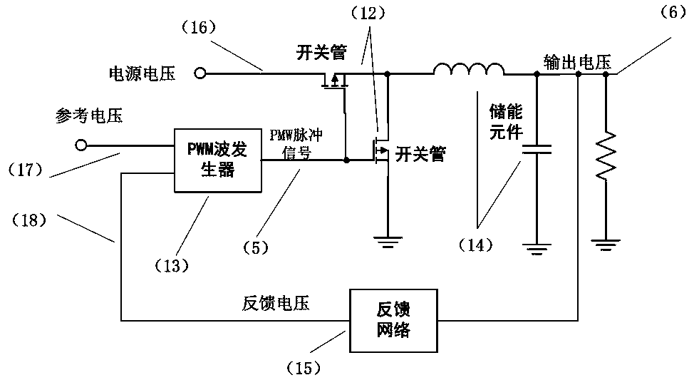
[0047] Such as image 3 as shown, image 3It is a classic BUCK switch circuit, including a switch tube 12 , a PWM wave generator 13 , an energy storage element 14 and a feedback network 15 . The output voltage 6 of the switching power supply generates a feedback voltage 18 after passing through the feedback network 15, and the PWM wave generator generates a PWM pulse signal 5 according to 18 and the reference voltage 17; An output voltage 6 is thus generated across the energy storage element 14 and the load.
[0048] Figure 4 In order to combine the BUCK switching power supply circuit of the circuit of the present invention, 20 represents the circuit of the present invention, and at the same time, this patent also needs to use the switch tube array 19 to replace 12 in the classic BUCK switching power supply circuit. Among them, the switching tube control bus 8 output by 20 will determine the number of switching tubes in working state in 19, assuming that the larger the val...
PUM
 Abstract
Description
Claims
Application Information