A piezoelectric electromagnetic composite vibration energy capture button battery

A composite, piezoelectric technology, applied in the direction of piezoelectric effect/electrostrictive or magnetostrictive motors, generators/motors, electrical components, etc., can solve the problems of difficult integration, poor environmental adaptability, and failure to meet the requirements of electrical devices demand and other issues

Inactive Publication Date: 2019-01-04
长春吉威新能源科技发展有限公司
View PDF1 Cites 3 Cited by
  • Summary
  • Abstract
  • Description
  • Claims
  • Application Information

AI Technical Summary

Problems solved by technology

[0003] In order to solve the problems of low power density, poor environmental adaptability, difficulty in integration, and inability to meet the needs of electrical devices in the current general piezoelectric self-generating structure, a piezoelectric-electromagnetic composite vibration energy-harvesting button battery is proposed. The composite vibration energy harvesting button battery consists of the battery top cover, battery case and magnetic battery base to form the external structure of the cylindrical button battery. The interior of the battery is composed of gaskets, springs, hollow shafts and composite piezoelectric cantilever beams to form a vibration energy conversion structure. The device not only changes the structural form of the traditional piezoelectric cantilever into an array fan-shaped piezoelectric cantilever to make full use of the internal space of the battery cylinder, but also changes the mass block at the end of the piezoelectric cantilever to a ring coil, and the piezoelectric cantilever vibrates At the same time, the toroidal coil generates induced current due to the change of magnetic flux

Method used


Image

  • A piezoelectric electromagnetic composite vibration energy capture button battery
  • A piezoelectric electromagnetic composite vibration energy capture button battery
  • A piezoelectric electromagnetic composite vibration energy capture button battery

Examples


Embodiment Construction

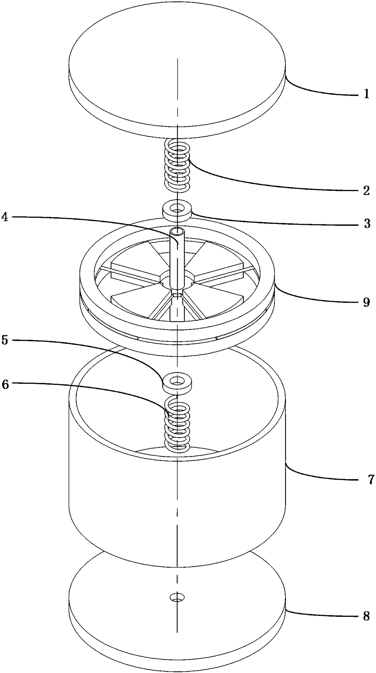
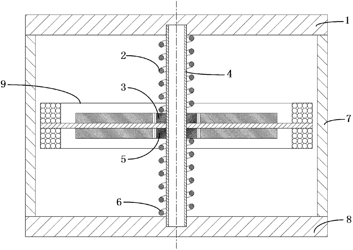
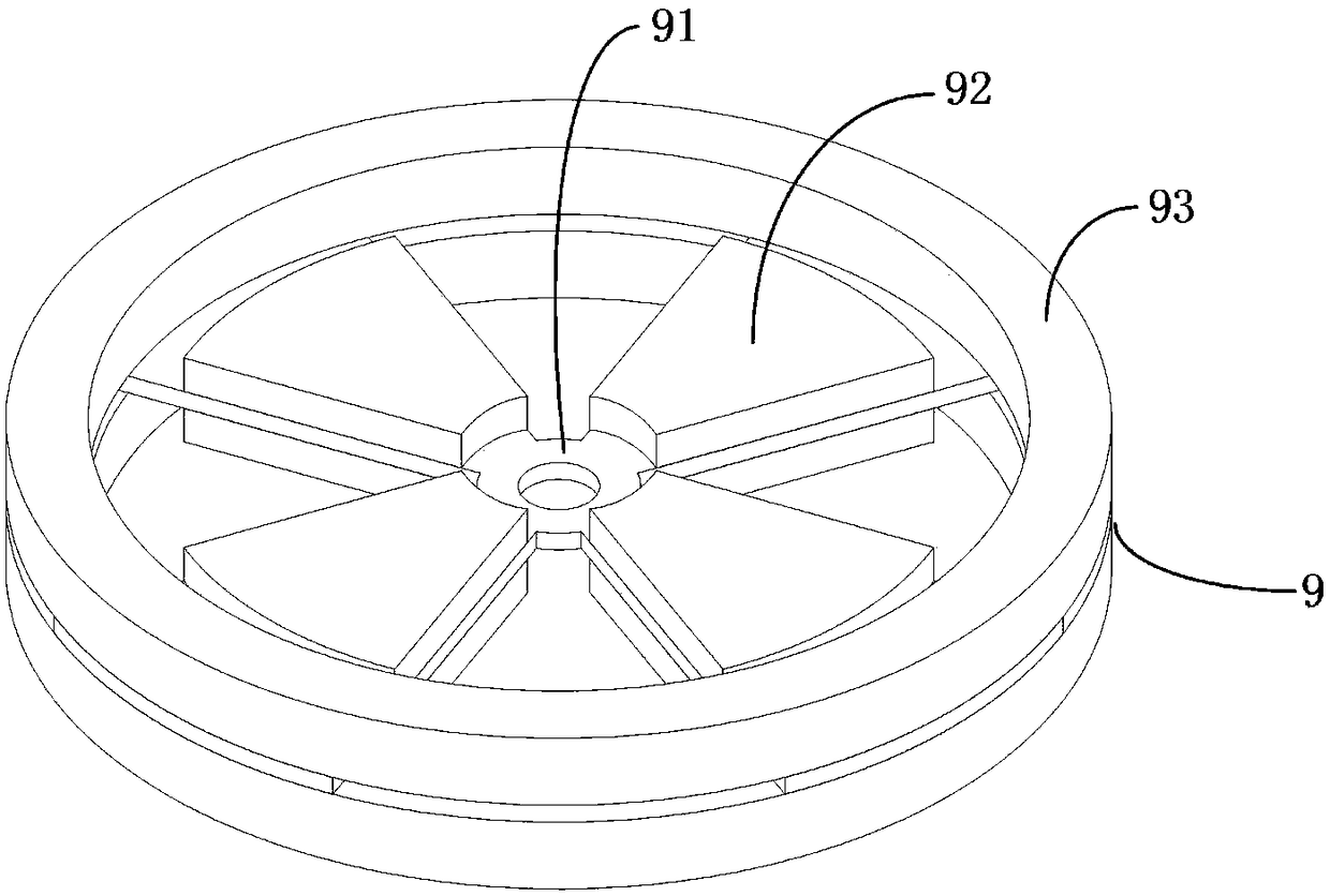
[0011] refer to figure 1 , figure 2 and image 3 , a piezoelectric-electromagnetic compound vibration energy-capturing button battery of the present invention consists of a battery top cover (1), an upper spring (2), an upper washer (3), a hollow shaft (4), a lower washer (5), a lower spring (6), battery casing (7), magnetic battery base (8) and composite piezoelectric cantilever beam (9), wherein: the battery top cover (1) is a disc-shaped member, and a circle is arranged in the middle of the bottom surface The center of the outer end surface of the battery top cover is equipped with an electrode; the magnetic battery base (8) is a disc-shaped member, and the circular sinking groove arranged on the top surface is in the same direction as the circular sinking groove on the bottom surface of the battery top cover (1). Yes, an electrode is installed in the middle of the outer end surface of the magnetic battery base; the battery casing (7) is a cylindrical shell, the upper en...


PUM


Abstract

The invention relates to a piezoelectric electromagnetic composite vibration capture button battery, comprising a battery top cover, an upper spring, an upper washer, a hollow shaft, a lower washer, alower spring, a battery case, a magnetic battery base and a composite piezoelectric cantilever beam, wherein, the battery top cover, the battery case and the battery base constitute a sealing cavity;the upper spring, the upper washer, the composite piezoelectric cantilever beam, the lower washer, the lower spring and the hollow shaft constitute a piezoelectric power generating device. When the device vibrates, the composite piezoelectric cantilever beam vertically vibrates, the piezoelectric patch generates electricity, at the same time, the induction current is generated by the end part coil winding of the composite piezoelectric cantilever beam due to the change of the magnetic flux, the piezoelectric power generation and electromagnetic power generation energy is collected to the button battery, and the button battery is used in the fields of micro-electromechanical systems, wireless sensors and the like, and has the advantages of good energy collection efficiency, no need for maintenance, long service life, energy saving and environmental protection, easy integration, strong environmental adaptability and the like.

Description

technical field [0001] The invention belongs to the field of piezoelectric power generation, and in particular relates to a piezoelectric-electromagnetic composite vibration energy-harvesting button battery. Background technique [0002] With the development of science and technology, self-power supply technology occupies an increasingly important position in the fields of micro-electromechanical systems, precision machinery, intelligent machinery, wireless sensors, biomedicine, aerospace and other fields. At the same time, people pay more and more attention to the concept of environmental protection. Therefore, there is an urgent need for a new energy battery that is easy to integrate with tiny machines to replace traditional dry batteries, button batteries and lithium batteries. With the development of piezoelectric power generation technology, piezoelectric self-generating devices with piezoelectric ceramics as the core functional material stand out. However, there are f...

Claims


Application Information

Patent Timeline
Patent Type & Authority Applications(China)
IPC IPC(8): H02N2/18H02K35/04
CPCH02N2/18H02K35/04
Inventor 吴越刘清华韦东东陈全渠马文瑞
Owner 长春吉威新能源科技发展有限公司
Why Eureka
Try Eureka