Turbomachine housing

A technology for turbine shells and shells, which is applied to mechanical equipment, engine components, machines/engines, etc., and can solve the problems of offsetting the tightness of the flange connection, the influence of the tightness of the flange connection, and unfavorable lever conditions. achieve good tightness

Active Publication Date: 2019-01-04
MAN ENERGY SOLUTIONS SA
View PDF6 Cites 0 Cited by
  • Summary
  • Abstract
  • Description
  • Claims
  • Application Information

AI Technical Summary

Problems solved by technology

[0005] The greater this offset Δx between the effective direction of the force vector 12 of the corresponding bolt force and the effective direction of the force vector 14 of a force dependent on the pressure in the interior of the turbine housing 1 , the greater the The more unfavorable the leverage conditi...

Method used


Image

  • Turbomachine housing
  • Turbomachine housing

Examples


Embodiment Construction

[0017] The invention relates to a turbine housing, in particular a steam turbine housing.

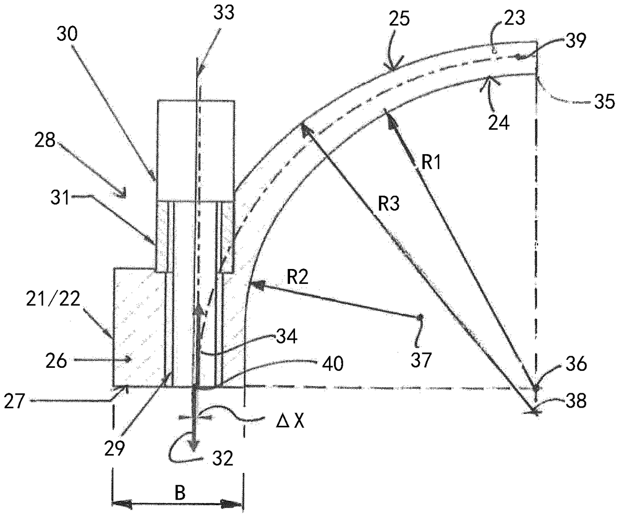
[0018] figure 2 A preferred exemplary embodiment of the turbine housing 21 according to the invention is shown in the region of the second cover-like housing part 22 which is connected to the bottom of the turbine housing 21. The first lower shaped housing part is shown. Shown is a curved wall 23 of a cap-like cylindrical shell-like housing part 22 comprising an inner side 24 and an outer side 25 which are curved in cross-section.

[0019] The illustrated cover-shaped housing part 22 of the turbine housing 21 comprises a flange 26 with a flange surface 27 , wherein the flange surface 27 of the flange 26 of the cover-shaped housing part 22 passes through the turbine housing 21 The not shown lower housing parts are connected to corresponding flange surfaces, and wherein these housing parts are then connected to each other via screw connections 28 . Each of the bolted connections 28 in...


PUM


Abstract

The invention relates to a turbomachine housing (21), in particular a steam turbine housing, comprising a first housing part and a second housing part (22) which are connected together via screw connections (28) on opposing or adjacent flanges. The second housing part (22) comprises a curved wall (23) with a curved inner face (24) and a curved outer face (25). The invention is characterized in that the curved inner face (24) is contoured with a first curvature radius (R1) in a first region facing away from the screw connections (28) and with a second curvature radius (R2), which deviates fromthe first curvature radius (R1), in a second region facing the screw connections (28) such that a force vector (34) of the force which depends on a pressure in the interior of the turbomachine housing(21) runs approximately coaxially but opposite to a force vector (32) of the screwing force of the screw connections (28) in the region of the screw connections (28), said screwing force vector extending through the axis (33) of the screw connections (32).

Description

technical field [0001] The invention relates to a turbine housing. Background technique [0002] A turbine housing, such as, for example, a steam turbine housing, usually consists of a plurality of housing parts, in particular a first lower housing part and a second cover housing part, said first lower The cover-like housing part and the second cover-like housing part are connected to each other via bolt connections on flanges positioned opposite or adjacent to each other. [0003] figure 1 A cross section through a turbine housing 1 known from the prior art, ie a steam turbine housing, is shown in an excerpt in the region of the cover housing part 2 . The cover-like housing part 2 has a wall 3 curved in cross-section with a curved inner side 4 and a curved outer side 5 . In the edge region of the cover-shaped housing part 2 a flange 6 is formed which has a flange surface 7 which connects the adjoining flanges of adjacent housing parts which are not shown. figure 1 The c...

Claims


Application Information

Patent Timeline
IPC IPC(8): F01D25/24F01D25/26
CPCF01D25/243F01D25/246F01D25/265
Inventor C.M.福斯特J.霍曼F.布拉姆
Owner MAN ENERGY SOLUTIONS SA
Why Eureka
Try Eureka